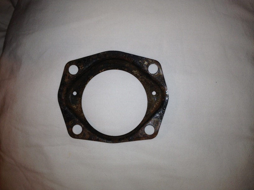
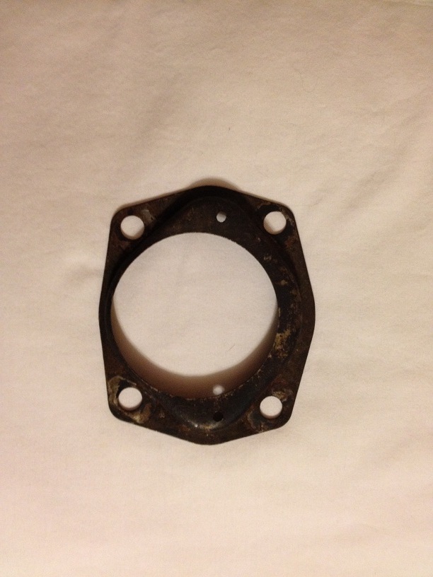
I have a question that I haven’t been able to answer with either the intermediate shop manual or the Google: Between the old wheel hubs and the drum brake shields there was a metal piece with a felt gasket behind it. It seemed to space the wheel hub out a bit. Does anyone know what this is called or what purpose it serves? There was no way to reuse it and no replacement for it in the conversion kit I used.
No one knows what this is?
And this is where it gets rocky… You used some kind of conversion kit that hopefully works out okay, but for what ever reason the kit folks must have either accomplished what this piece does in some other way, or decided that Ford didn’t know what they were doing in the first place. You would need to talk to the kit people to see why they left this piece out. When you start modifying the car, you become the engineer who decides what things are important. Its kind of like trying to use the factory tune up specs for a modified engine, they no longer apply.
I believe that the piece you have pictured is a shield that keeps water and other undesirable stuff away from the bearings and out of the interior of the brake drum. Since you are converting to disc brakes, it makes sense that the excluding trash from the entering the drum might not be needed. I would check with the kit folks and see what they can tell you.
Well, let’s hope it doesn’t get too rocky. This is the hub backing plate with a spindle gasket. According to West Coast Classic Cougar and another fellow on a different board, this is not needed with disc brakes. Thanks to the helpful folks out there, I appreciate your assistance!
I hate having parts left over… Glad to hear that he WCCC guys knew about this.
Front discs installed successfully, rear drums brakes rebuilt and drums painted to match the car. New 17" aluminum rims and 245/40 tires ready to go on as soon as I install the new master cylinder and bleed the system. Grille is going back on with electric motors mounting, still wiring up the harness, though. I think I am going to remove the power steering (that’ll eliminate one sizeable fluid leak).
I have a Pertronix Flamethrower coil and the Ignitor to replace the points. Has anyone wired up a coil that needs the full 12 volts? I’ve read a bit about the infamous resistor “pink wire”, but can any of you skilled doityourself Cougar guys give me any assistance with this? When these are installed, I’m putting in new 8mm MSD plug wires and new Autolite Copper plugs. Recommended gap on the plugs for a 289 4v?
I’m ready to get her back on the road for a little while. I can tell the old cat needs to prowl around outside of my garage. Down the road, I’m looking at a 408 stroker and AOD.
Well, I decided not to use the 8.8 inch rear end. Posted it on craigslist last night. I believe I am going to stick with the 8 inch for now and just replace the 2.73 third member with a set of 3.55s or 3.80s. Anyone got a good, solid used one for sale? I suppose I could spend $1000 bucks on a new one, but I really don’t wanna. Thanks.
When I switched to the Ignitor II, I had to run 12v to it. I ran a wire there from inside the dash, at the end of the pink wire where it’s still 12v. Initially I just unplugged the pink wire and pushed a stripped wire end in between those two connectors and pushed them back together, which worked fine but wasn’t a very proper long-term solution. More recently I bought some barrel connectors at AutoZone and wired up a little T, with one male and one female barrel connector and the wire going to the Ignitor soldered in between them. That way I have a good proper sort of connection, and it’s 100% reversible with no damage to the wiring harness or resistor wire. And then that wire runs out through the firewall, along the bottom of the passenger side shock brace, and crosses over to the engine. People have commented on how bad it looks, since I used a white wire. Personally I have no problem seeing it, so I have no plans to try and do a more hidden install. Probably could’ve run the wire along the driver’s side top of the intake manifold, like where the wiring stub for the coil and temperature sensor runs.
The Pertronix is one of the best simple mods ever in my opinion. But there still seems to be a lot of mystery about making it work.
There are just a few very basic issues that need to be understood, and then I think everything else falls into place.
The back story: How this stuff works, or doesn’t.
The higher the voltage, the larger the gap a spark can jump. In the case of a set of points you don’t want a spark across the points gap when they are open. A spark is very, very, hot. Typically 4 to 5 THOUSAND degrees. The good news is that the area that gets that hot is also very very small. Never the less, as the points open and close the gap is narrow and a small amount of voltage can be enough to generate that little spark. The spark tends to burn away the contact points over time. This is why we call a bad set of points “burned”.
To reduce the amount of voltage being switched by the points, it was common engineering practice to use an inline resistor, sometimes called a ballast resistor, so that the points would only have to switch about 6 to 8 volts instead of the 14.4 that your alternator should be putting out. Cougars have what is called a resistance wire that serves this purpose. Typically it is the pink wire you find under the dash. Many times this wire is covered with an additional layer of cloth like insulation. The purpose of the cloth is to keep the resistor wire, which gets hot in operation, from heating up other things under the dash.
So for a set of points, running a lower voltage works well when the engine is running. But there is a problem during engine cranking when you are trying to start the engine. The battery, when fully charged is at 12.6 volts, already down about 2 volts from what the alternator produces when the engine is running. And then the starter motor is very nearly a dead short, so when the battery is trying to supply the current the starter needs, the voltage drops even more, sometimes to less than 9 volts. So we really don’t want to drop this voltage even more by running it through the resistor wire.
The engineers figured out a nice by pass to get more voltage to the points during cranking. There are two terminals on the side of the starter solenoid. The one on the same side as the starter cable connection is only electrically hot during engine cranking. The wire going from this terminal goes to the points and bypasses the resistor wire. I mention this here because it can give us a huge clue to a trouble shooting a common problem: the engine kicks over during cranking and then dies when you release the key. What this is telling us is that the voltage from the bypass circuit is adequate to run the car, but the voltage from the resistor wire is not.
To be continued
Holy moley! That’s some mighty fine info there, my friend! Can’t wait to read part two! Much obliged!
Now you know why the original points / coil ignition is being supplied with a lower voltage: to eliminate sparks at the points. But that voltage being switched on and off by the points, is also feeding the coil. The purpose of the coil is to step up the voltage so it can jump the relatively huge gap at the spark plugs. As it turns out this is not that big of a problem because the voltage output of a coil can be increased by changing the number of turns (this is why they call it a coil remember?) of wire inside the coil. In general to increase the output of a coil you decrease the number of turns being fed by the battery, and increase the number of turns feeding the spark plugs. So for any coil design , there is a ratio of output voltage to input voltage.
Things would be simple if voltage was our only concern. Electrical power has two parts voltage, and current. Electrical power is measured in watts, and you can figure out how many watts of work you can do by multiplying voltage times current. Less of one is okay as long as you have more of the other. IF we need a certain amount of power to do the work we want, like to get a big fat spark to jump a spark plug gap, and we have limited amount of voltage, then we are going to need more current. More current also means we need bigger wire with less resistance so we don’t end up heating up the wire instead of doing the work. This is important to know because when the engineers design a circuit, the design it around a given maximum amount of current that everything needs to handle. Try to run too much current through the circuit and you will blow the fuse, or burn something up. There are no fuses in the ignition circuit so burning stuff up is your only option.
Okay so tell me how to hook the blessed thing up already!
The Pertronix Ignitor is really like a little switch that is being turned on and off by a magnetic pulse (that little black ring thing that you put on the distributor shaft has magnets in it). The magnetic pulse has to be amplified in order to make the pulse strong enough to trigger the switch on and off. That amplifier and the switch itself (actually a type of transistor called a MOSFET) are both designed to operate using 12 volts. So they need their own power source to operate. The red wire on the Pertronix, needs to go to 12 volts not the 6 or so you get from the coil feed wire. Now this wire needs to be hot not only when the key is in the on position, but also during cranking. You also don’t want it to be hot when the key is in the accessory position. There are just not many places to get power that meet these criteria, but the ideal one is the wire (Red with Green stripe) that comes out of the switch that goes to the tach on an XR-7 or the Pink wire on a standard.
Now here is my trick for doing a clean install: Get a small piece of brass tube with a large enough diameter to pass the new power wire through the center. The tube only needs to be a few inches long. Sharpen one end. I just spin it against a grinding wheel. Stick a small pick or Phillips screw driver through the center of the tube. Now poke the pick / screw driver through the rubber grommet that carries the engine harness through the fire wall from inside the engine compartment. Be careful not to hit any other wires, and stay close enough to the center to make sure you go through the whole in the sheet metal. It will take a bit of force as the rubber is probably pretty hard after 45 years. Take your time, open a beer. Once you get it through, remove the pick, leaving the tube in place. Run a new wire ( use 18 gauge 105* C wire from Radio Shack) through the tube. Run a bunch through as it will make it easier to find on the inside. (The hardest part is finding the blessed wire under the dash.) Then once you have found it, connect it to the Red with Green stripe wire. Under the hood, pull the tube out of the rubber grommet, and slide it down and off the wire. You are almost there. You deserve a beer about now.
Under the hood you will connect the new wire you just installed to the red wire on the Pertronix, and only to the red wire. Leave the factory power feed wire (+) wire on the coil. Connect the black wire from the Pertronix to the negative post on the coil. The Pertronix is switching the ground on and off not the power. This part is optional, but when you connect the red wire from the Pertronix to the new wire you might want to use a male and female insulated bullet connector. (The female side is the hot side. That should be easy to remember) If you unplug this, your car won’t start. These cars are so easy to hot wire and steal that I really like having a very low tech way to defeat the average thief.
Okay so now you have eliminated the points. Have another beer. WOOHOO! On to the coil. OR maybe not. On our cars I would recommend you stay with the Flame Thrower 1 coil, leave the resistor wire in place, leave the plug gap where it is, and call it good.
The problem with adding a higher voltage coil is that it also means you are increasing the amount of work to be done. That means more current. More current means more heat. Some parts of the circuit are not designed to handle any more current. Like the tach in particular. And don’t think about getting rid of the Pink resistance wire. The tach will read too high until it burns up. The Flame Thrower 1 coil will work as it has 1.5 ohms of internal resistance. The Flame Thrower 2 has only .6 ohms internal resistance so you are potentially pulling 24 amps of current (14.4 /.6) through a bunch of 8 amp parts. Be sure you have good insurance.
Now if you are determined to run the biggest ignition you can find, fear not. You can run one of Rocketman’s three wire tachs, and then install a relay to switch a new much higher current circuit to deliver all of the current you might need. In hot rodding there is always a way!
Hope that helps.
One more thing. Will the Pertronix work hooked up straight to the coil? The answer is: sort of.
Most of the time it will work. During the most critical start up period it is getting the right voltage due to the by pass. When you are driving the car the alternator will probably hold the voltage high enough that it will probably run more or less okay. Where you notice the difference is at idle in particular if you have the heater, headlights or AC running. In severe cases the engine will die at idle and then restart perfectly. I have seen people bump up idle speeds to try to “fix” the problem not knowing what the real problem was. There are guys who have been driving cars wired like this for years that swear by it. I also know of people that have burned up three or four Pertronix units because they were wired this way that think the Pertronix product sucks. Wired to twelve volts I have never had a failure and at the moment I am running 8 of these on different cars.
A long time a ago a very good electrical engineer and also Cougar guy wrote this:
From: Eric Overton
Date: Mon May 31, 2004 3:50 pm
Subject: RE: [COUGARS] Pertronix Wiring Result and a Question
The Pertronix was designed to run on 12V, and if anything it will last longer running that way than it will at 6V.
The reason is that the Pertronix isn’t what supplies the “+” terminal of the coil (which should always be at 6V
except when momentarily bypassed by the starter relay). The Pertronix is a switch that interrupts the connection
between coil “-” and ground. And like all switching devices, it wants to be either “on” or “off” and doesn’t like to
be hanging in some in-between state. The speed with which the switching action takes place is greater when the
device’s supply voltage is higher, so 12V is vastly preferable to 6V. Mind you, I’m talking very specifically about
the positive voltage supply to the Pertronix and not to the coil.
To get an idea what slow switching does to a switching device, go to any light switch in your house and very,
very slowly flip it on until the lamp just barely starts to flicker. And when it does, listen to the sound coming out
of the switch. If it sounds like something burning, that’s because it’s something burning. The transistor switch in
the Pertronix doesn’t have mechanical contacts, but in many respects, the effect is much the same. When it’s all
the way “off,” it’s resistance is infinite, so the power it’s being asked to dissipate is zero, since Power = Voltage /
Resistance^2. When it’s all the way on, the voltage across it is effectively zero, so again Voltage / Resistance is
also zero. But when you’re somewhere in the middle, voltage across the switch can be bigger than zero while
resistance is something less than infinity, and the result is that the power the switch is asked to dissipate is at its
maximum --shortening its life.
Bottom line: Powering the Pertronix at 12V will push the switch through the “half on” condition more quickly than
if it only has 6V behind it, so the period of time in which it has to dump power through itself instead of routing it
through the coil circuit is much reduced. And when the instructions say “connect this to 12V,” there’s usually a
reason.
Wow! I’m impressed! A veritable dissertation on the ignition system! Thank you very much! That definitely straightened me out. Somebody should make a sticky out of that, I think.
Many thanks to xr7g428 and his complete explanation of installing a Pertronix Ignitor and Flame Thrower 1 in our early Cougars. Both are now installed and functioning in my 67 XR7. It does seem to idle smoother now. Haven’t had a chance to get on the road with it since (still working on the brake system), but I am confident that it will be good. Now, once I get the brake system done and finish the reassembly of my grille, I can get the car on the road and enjoy driving it around for a while before I start on my next sub-project with it.
For my next question…my power steering pump and/or components leak all over the place. I can’t tell as yet where exactly the leak may be. Should I try a seal kit from WCCC or get a manual steering adapter and just remove the pump altogether? I’m sure many of you have been down this road and have some opinions on this issue. Thanks!
By the way, the ol’ XR7 is running pretty good and stopping quite well, too. I converted to disks on the front and swapped out the master cylinder (twice…the first one was a reman which was leaking out the back, the second was a new one and is working fine). I had to bleed the system a few times and finally bled it while the engine was running, which finally did the trick. I was starting to get worried! Now it is on to tracking down and fixing the leaks. The power steering is the biggest leak, followed by a small transmission leak…somewhere.
Still, the Coug is running better and stronger than I thought it would. I figured it would be quite a bit slower off the line with the 2.73s in it than it actually is. The Pertronix ignitor and repair of a plugged up vacuum advance line did the trick. New plugs, plug wires, and a Pertronix Flamethrower I also helped. After the vacuum advance line was unplugged (an unidentified round piece of metal was in the line), she was idling high, but much smoother. Turned the idle down and it’s all good. The new wheels and tires ride much better than the old 14" steelies. I’m kinda happy with it!
Fixing the power steering is your best bet. The fix is really not that difficult. start out with a new set of hoses. Use the big block (FE) kit regardless of what your car came with as the install is much cleaner and easier than the small block kit. The line seats in the control valve seem to be the ones that cause the most trouble. You can get the old ones out buy running a self tapping screw into the seat and then pull it out with pliers. You can get replacement seats at NAPA. The hoses really don’t have to be tightened super tight if new seats are used.
The control valve is pretty easy to take apart and rebuild and check for wear. There is a complete rebuild kit that is relatively cheap. The seal in the ram is also easy to replace. You will need a pick with a right angle bend to help pull the old parts out. The rubber accordion boot that cover the rod coming out of the ram should always be replaced as it keeps the crud out that causes the seal to fail to begin with.
Using the power steering eliminator kit is a poor choice. On manual steering cars the steering box in most cases has a slower ratio (19:1 versus 16:1) to make the steering a little easier (exception is the GT with manual steering). The slower ratio is designed to reduce the effort needed to turn the wheel. A 390 with manual steering is a bear to park. The steering box is really just the first thing to consider. Manual steering cars have different steering geometry that involves a different drag link, Pittman arm and steering box arm. All of this is designed to reduce the amount of force you have to apply to the steering wheel to turn the car. So the quickie conversion is much harder to steer than even the factory manual system. I have my doubts about how the increased load is handled by the steering column.
And while we are working on the front end, keep in mind that in '67 Cougar and Mustang are not the same. The Cougar used an articulated strut rod and Mustang did not. this means that the mounting holes o the lower control arms are drilled in different places. If you don’t plan on replacing the strut rods, then be sure to get Cougar lower control arms. I think the articulated arms are kind of cool so I might go to the trouble of rebuilding them and going all Cougar, but the easy solution is to replace the strut rods with '68 Mustang or Cougar parts and then use the '68 common style lower arm. The value of the concours parts is not the paint, it is the deeper, better formed steel components.