Well, sorry, but I can’t remotely diagnose a low fuel light thats been converted to LED and only flashes during cranking. But something is not right in that circuit either. My advice for the fuel gauge is to start with something that is known good. Bill’s rebuilt fuel sensor should be all calibrated and ready to go. Next step for me would be to use Bills gauge tester to establish if the gauges are all working correctly over their full range.
That is kinda of what I was thinking.
1 Like
What does the fuel gauge read with and without sender plugged in? Just donned on me that the gauge could be shorted to the metal gauge cluster housing.
Already checked that. It is 50 plus ohms on each post.
Check the polarity on your low fuel LED. I am thinking the flashes when you engage and again when you release the starter could be due to very fast negative voltage spikes due to inductance when the starting solenoid engages and disengages. The circuit was designed around an incandescent lamp and I bet the low fuel light with a bulb would stay lit while cranking as intended.
You LED me in the right direction. Turns out the bulb holder is shot. Switched holders and the fuel light is bright as can be grounded.
I will order a gauge tester from Bill and see what is going on with the fuel gauge unless you have another test I can try.
The gauge moves when the lead is grounded but no movement when the grounded sensor arm is moved into the middle or full.
I will check to see if the Low Fuel Light comes on with the arm at empty.
Order another bulb holder from WCCC. Seems like I am ordering one little part every few days. I will get a couple of them!
I have been watching this. Some good tips here. There are a few things that need to be addressed.
The fuel sender has two variable resistors as part of two different circuits.
The fuel level part is powered by either pulses of 12 volts, that average out to 5 volts over time (this is how it works from the factory with the factory instrument voltage regulator) Or it may be powered by a solid state reproduction voltage regulator that puts out 5 volts continuously. In either case the power is routed from the IVR to the gauges. Fuel, Temp and Oil Pressure share the feed. A problem with the IVR will effect all of the gauges. The other side of each gauge is grounded through a variable resistor. Internally the gauges are identical and the senders for temp oil pressure and fuel level operate over the same range of resistance. This is how the gauge tester can test all of the gauges.
The low fuel circuit is completely independent. It is powered by 12 volts when the key switch is in the run position. Thermistors are temperature sensitive resistors. In this case it is a Negative Temperature Coefficient thermistor (NTC). This means that as temperature rises resistance goes down. In this application the thermistor is self heating. When it is submerged in gas the fuel acts as a giant heat sink to keep it cool. When it is in air it heats up and the resistance allowing more voltage through the circuit. When the voltage rises high enough it creates enough magnetic force in the coil in the relay to pull down the switch that connects the lamp to the power supply. During cranking a wire from the starter side of the solenoid bypasses the relay and lights the lamp. It is called the prove out lead: it proves the lamp works.
Keep in mind the low fuel light has nothing to do with the fuel sensor float position. Completely separate circuits. Low fuel light is controlled by the thermistor in that bullet shaped housing on the fuel sensor. Also, the best way to test the low fuel led is that it should be on steady and bright while cranking the engine.
1 Like
The gauge tester is the right diagnostic tool for this circuit. You connect two alligator clips and it will verify exactly what the problem is.
But let’s ignore that and move on with how to troubleshoot the circuits with things you might already have. What we are concerned about first is getting power to the sender. You can use a test light to check this. Put the key in the accessory position. (Putting the key in the RUN position, without the engine running, can overheat your coil or damage Pertronix 1 so don’t do that!) Attach the ground lead of the test light to the flange of the gas tank where the sender goes. With an XR7 you will have two wires to probe. One should have a continuous 12 volts. That is the low fuel wire. The other should have a flashing 12 volts or a dim continuous 5 volts. If you don’t get this result you need to first move the black ground lead to see if your tank is no longer grounded. (typically after the car has been restored and everything is painted) If that doesn’t fix it you have to move to the first harness connection in the trunk and verify you are getting the same results there. The next step is behind the instrument cluster.
It is very important to note that testing for voltage with a meter DOES NOT work. The pulses will drive your meter nuts. They occur two far apart in time for the meter to average them. Then there is this. When you are looking at voltage in an open circuit what you see is potential voltage. There can be a very high resistance connection in the circuit but it won’t effect voltage because no current is being passed through that connection. It’s ohms law. The lamp in your test light is the load you need.
Now your meter is a great tool and this is where you can use it. It is exactly the right tool to measure resistance. You will want to put it on the lowest scale (probably 200 ohms on most hobby grade multi meters). The first thing to measure is the resistance from the output pins on the sender to ground. If you have an XR7 you have two that you want to measure. The fuel level should measure very close to 10 ohms with a full tank or the float arm in the fully up position. Hobby grade meters are not all that accurate at low resistances like this so it might be a little off. Then with the float arm in the fully down or empty position you should measure at least 60 ohms. More that 73 might indicate a problem. If you are seeing these numbers then the sender is working. The other pin will depend on the temperature of the thermistor. What you really want to see is that there is continuity. Thermistors mode of failure is to an open circuit, so if you see that there is not continuity then the thermistor is bad.
Keep in mind the gauges are designed to respond fairly slowly to changes in inputs. They work by heating up bimetallic strips that bend and then move the needle. So it can take up to 30 seconds for the gauge to respond to a change. This is very intentional. It keeps the needles from looking like the VU meter on a tape deck when fuel sloshes around in the tank.
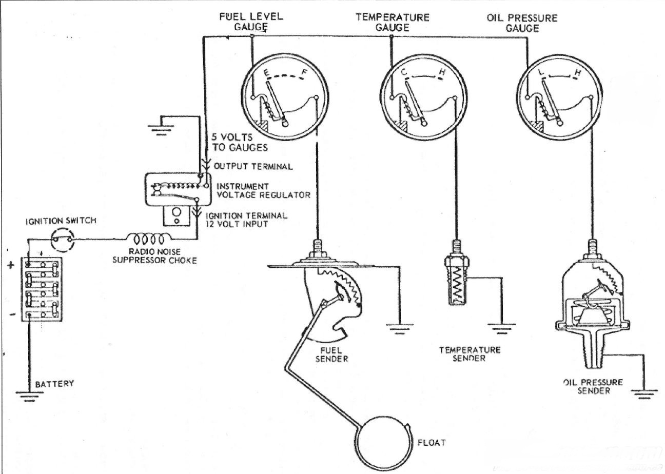
The one misleading thing about this is that is shows 5 volts to gauges. That is correct but only when averaged over time.
I use an old bench top John Fluke meter that is ridiculously accurate to measure senders during calibration. However that is not testing under load. So I use the Ford factory circuit to test each sender before it leaves. Given all of that, things still go wrong. I warranty my work so if there is a problem I will fix it.
I am wondering if the plug is making a good connection to the sender. It might be instructive to see if you can use some clip leads to verify it. Some times the brass inserts in the plug can be too big to make the connection and need to be squeezed a bit.
Along those lines, it sounds like the low fuel part is working correctly: sender plugged in and grounded, key in accessory position. Low fuel light comes on a stays on after about 15 seconds or so. Can you confirm this?
Now I have more to explore.
My fuel tank is not sealed and bolted into the trunk yet. I was using the tail light ground screw for my ground source.
At the gauge boot I have the following:
I have continuous 12 Volts at the Thermistor lead.
I have flashing at the gauge lead.
Steady Low Fuel when cranking.
I have 67 ohms at the Gauge Pin at empty. I have 9 ohms at full.
I have .24 ohms at the thermistor pin.
Those are correct readings for the sender fuel level.
I have 67 ohms at the Gauge Pin at empty. I have 9 ohms at full.
I suspect your meter might be auto ranging and shifting to the 1K ohm mode when you are measuring the thermistor as .24 is close to a dead short. So in the 1K ohm mode .24 is really 240 ohms. That is possible.
I have .24 ohms at the thermistor pin.
With the sender plugged in are you getting the low fuel light to light up after 15 to 20 seconds? might be longer if the battery is getting weak.
I do not get the Low Fuel light with the key in accessory.
But if you ground that wire at the sender plug it lights up?
I had the meter set at 2K
Yes
It looks like the plug is the issue. Or the ground to the sender. Use some alligator clip leads from the plug to the sender to verify you are getting a connection.