Very cool - got one ordered too, and thanks for the discount Bill! Amy chance it will also test the ammeter if disconnected from shunt? Mine just barely deflects under heavy charge.
Ammeter guts are completely different than the other gauges, so no, it can’t be tested with the machine. You can test it by applying (very briefly!) a 1.5 to 9V battery across the two posts.
I just ordered the gauge tester: very cool thing to have! You’re da Man!
Still thinking about how to test ammeters. What I find with them is high internal resistance.
Order placed! Very useful tool. Thanks for all your efforts on this.
Order placed. You’ll have to team up with Don and do a how to video with the tester for us electrical challenged owners.
Working on a video with Don and company right now
The fist batch is sold out. More are coming in about two weeks. I will post when they arrive. You can still place orders on the site if you want.
I just ordered one. A few weeks is not a problem. My pole barn in February in Michigan isn’t my first choice of places to be.
For those of us who are electrically inclined, what are your thoughts about supplying this as a kit?
For those of us who are electrically inclined, what are your thoughts about supplying this as a kit?
That is an interesting thought. I built Heathkit stuff as a kid, and even Hafler amps and preamps from kits. This product doesn’t lend itself to that. The PC board is stuffed and wave soldered in a machine. The individual components are all ordered on ribbons to fir into the pick and place part of the automated process. I think the only hand solder connection are the two leads. I think it would take more labor to assemble the kits than what goes into building it using the current process.
I wonder how many people even know how to solder at the board level these days.
Yup, I’ve done lots of board level soldering over the years, but wouldn’t attempt to hand assemble a board with today’s tiny surface mount technology. You are doing well to even make repairs with a soldering iron in each hand and a magnifying lens - if you don’t sneeze.
This will be a very helpful tool for a lot of guys. It’s rare when you see this kinda stuff come to market so kudos to Bill for putting in more time and effort then he will make off these!
I have repaired my fair share of electronics soldering on a board. Mostly without the right equipment but I always find a way to make it work. Most recently was swapping a usb printer port from a printer I sacrificed to repair part of our hunter aligner at my shop. Hey can’t make it any worse! It’s was already broke lol
Got mine in the mail today and ran out to the garage to check it out.
The instructions were really clear and easy to follow. My IVR tested out perfectly with the flashing blue light.
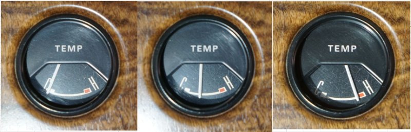
The temperature gauge tested out perfectly with the needle settling at cold, medium and hot for the corresponding tester settings.
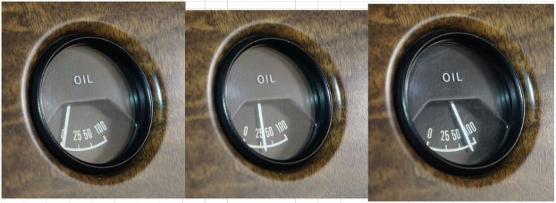
The oil pressure gauge showed bottomed out for low, a little over 25 for medium, and almost 100 for high.
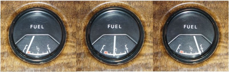
My fuel gauge showed right at the top of the red for empty, straight up and down for half-tank, but only showed 3/4 for full. This is the same way it reads with the sender (one of Bill’s rebuilt units) at those levels of fuel. So I need to figure out where the problem is. I guess it could be resistance in the circuit anywhere after the sender.
Check at the connection in the trunk. If it’s still low you can check at the gauge. Most likely the gauge needs to be recalibrated or replaced. At least now you know
Indeed. Thanks for developing such a great little device. I’m very happy to have it.
If you need to calibrate the gauge I maybe able to walk you through it
I peeled up the 2 inch cloth tape that was covering the connector in the trunk and found that it was not plugged all the way in. Separated the plugs, cleaned the connectors, and now my fuel gauge shows “FULL” for the first time ever.
I probably should have checked this connection sooner but the tape didn’t look like it had been disturbed before and I didn’t want to mess it up.
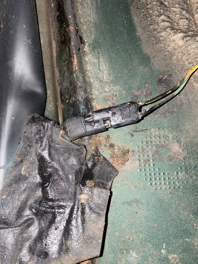
This is why I get the big money… LOL! That looks original. You were probably picking up about 10 ohms of resistance across that connection.
Again this is an awesome test tool. Here’s the results. Based on the instructions the gauges and vehicle wires all seem in good shape. Power LED would come on for about 2 seconds then begin to blink. Is it reasonable to judge that my gauges are all reading “slightly” low at each position? So the constant voltage regulator might be a bit on the low/lazy side?
Puts my mind at ease with regard to oil pressure. When running the gauge pegs at max. Only on the hottest days with the oil level on the low side have I seen it come off max at idle. The previous owner though it was broken but knowing the popularity (on FE’s) of high volume/pressure oil pumps, I assumed that was the real reason. Now I know for sure. [Viewed from an angle]
Similarly but less worrisome is the fuel gauge. Mine only goes up to about 3/4 tank when I’d fill it up. Hence the sending unit is on the fritz. I’ve mostly relied on the trip odometer and generally don’t run it to empty. [Viewed dead front]
Temp gauge seems fairly normal and works as intended thankfully. [Viewed dead front]
You have correctly diagnosed low voltage from the IVR. I like the modern solid state replacements
Used mine on my fuel gauge today. This thing is awesome!
My gauge pegs the needle on full, shows halfway between the 1/2 and 3/4 marks on the middle setting, and shows empty to be right at the right side of the low fuel red zone. I have a solid state IVR and it is showing 5.6 volts.
Looks like I have some gauge adjustments to make. At least now I know.![]()