1968 "Corrected" Wiring XR7 Diagrams Available Yet?

Greetings! Been a while. Here’s one for the old experts!!! Reader’s Digest version: “No charge condition.” If you don’t know what a Reader’s Digest is…Google it… :smile:

I’d changed alternators or swapped diode boards in MANY an alternator on this ol’ girl and she’d been working (charging) pretty darn good for a long long time! Butt… (every one has a butt…!)…working on my old 68 XR7, which now my son is it’s caretaker, and we just ran into a charging problem tonite after firing up his new engine in the car. NO CHARGE! Hmmmmm!?

He had taken pictures and videos of everything on the starter solenoid and the voltage regulator before we yanked the engine out. Swapped engine and trans, hooked everything back up with new 408W roller cam engine and TKO 5spd, with Pertronix Distributor and old electric choke and idle solenoid from the old carb.

I fixed a ground connection on the alt harness at the head, where those wires were getting a bit frayed…same with the green/red wire at the volt regulator. I had tapped into this years ago for the electric choke/idle solenoid and it has been working great, but the connection was also showing some fraying and broke off when I pulled on it a tad…too much! So fixed that too!

Patched up a nice flexible engine coil/gauge harness for the XR7 options as well, modified slightly to put coil on front of LH head. Wired in the Pertronix distributor as well. ( would have preferred to stay with DuraSpark II, butt hey, not my car any more!)

Engine fired up ok, but had some pesky fuel leaks due to stupid new Holley with center pivot bowls that takes one of hose chrome fuel rails that puts all your fuel connections on the RH side of the engine. Get’s crowded over there and I have NEVER like those chrome rails. Hate them even more after today…

First I had tried a nice used rail…leaked like crazy out of both connections no matter how tight I wrenched…may be slowed it down… Also had a leak at the front connection from my hardline to the rail…my fault…funky flare on the line…easily fixed later.

Fast forward to getting a new fuel rail from O’Reillys. Thru it on…still gushing from the front carb fitting. Pulled it all apart, looks like the fitting in the carb is damaged perhaps from rail #1.

Dug around in my carb parts and found a brandy new (older style) bowl fitting…takes HUGE wrench and you can’t get a good grip on it unless the bowl is off of the carb. UGH! …all we have for now…

Kept tightening more…leaks…more…leaks less…MORE…dribble…EVEN MORE…now we’re tight with a spot of dribble at higher RPMS. OK…need more tight…not tonite…found I left a tiny cork spacer that goes on top of fuel filter in the bowl fitting. Will revisit tomorrow!

SO, aside from the turmoil of leaks, checking timing, adjusting idle, float levels…things were going good! Oil pressure is reading good, temp gauge is moving…alt gauge never really worked for much…but at least the alternator/battery was always charging!

Now I get 12V or battery voltage minus a few tenths of a volt.

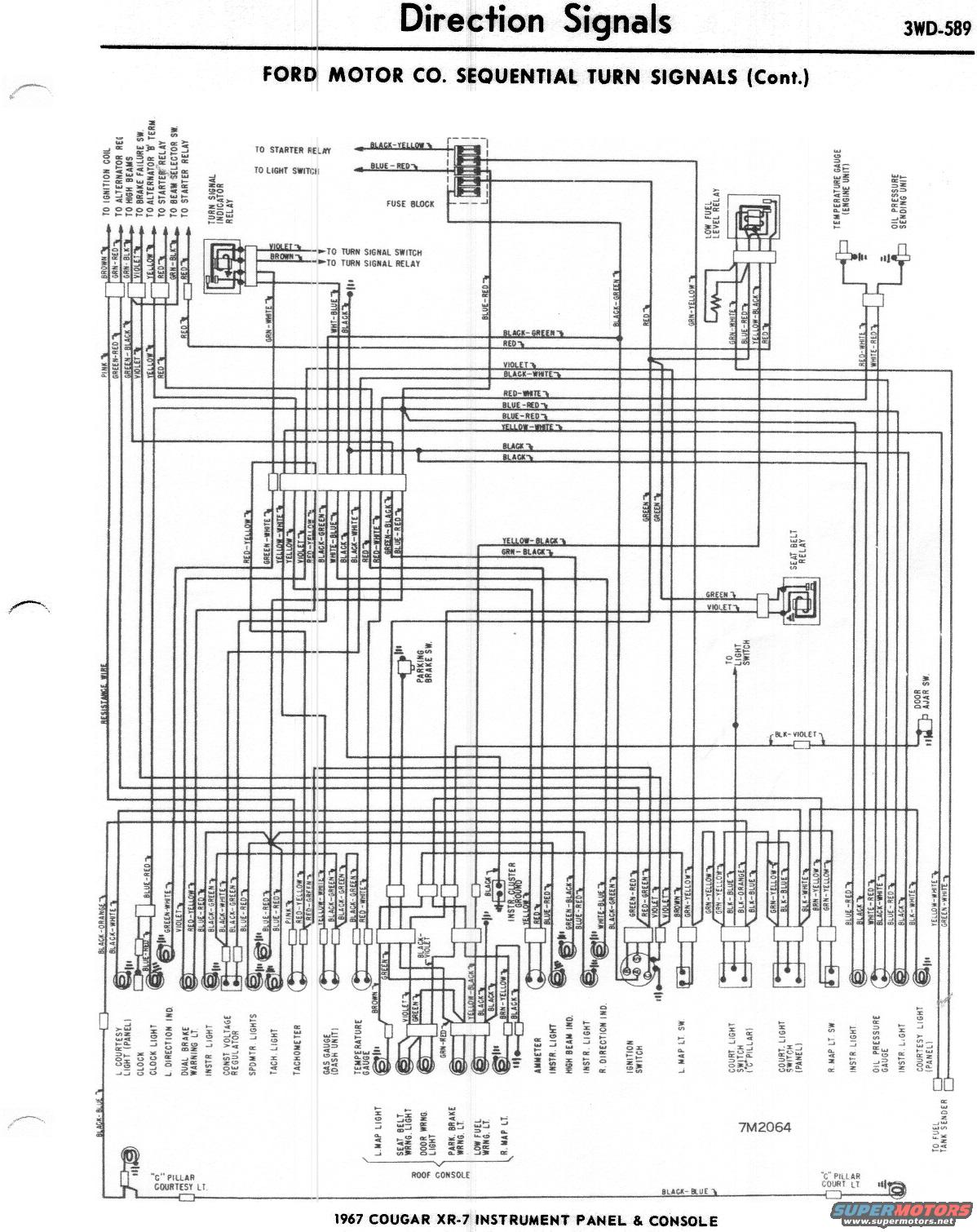
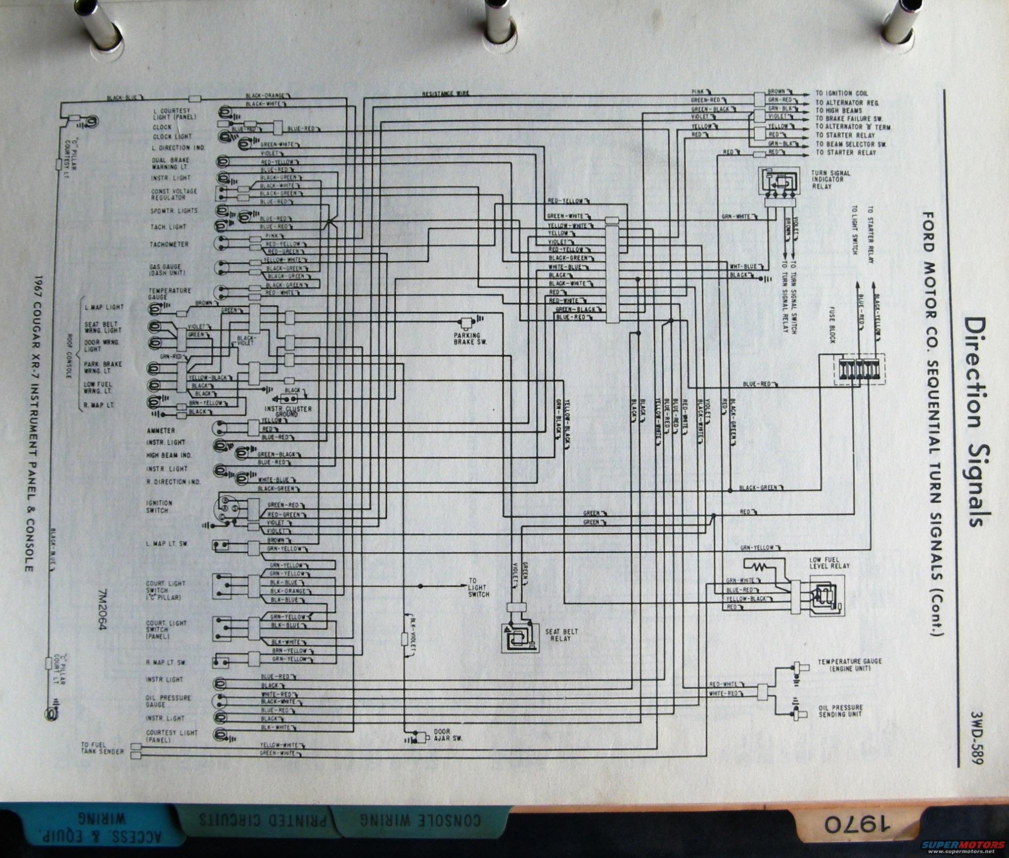
I dug out my trusty original Ford Wiring Diagrams Book for 1968 only to run into what I believe is a known issue where Ford never added the pages for XR7’s! All of the diagrams and wiring schematics seem to be for a standard Cougar!

The date on the bottom of the page is something like 9-1-67. I have some 67 drawings as well but didn’t bother to look. I did find the Mustang pages had different wiring for the cars with gauges vs cars with idot lights. (Standard version). But for some reason, the powers that be didn’t update the XR7 features!

What was also different was the colors of the wires…usually wrong…and out of position from Standard to XR7 in the drawings.

I jumped forward to 1969 diagrams which DID have the standard drawings as well as the XR7 versions…BUTT, the wiring colors are different. They seem to go to the same places…with a few more connections in between which can get a bit dicey following the wiring.

So barring a ground that isn’t grounding or a voltage connection that isn’t crimped like it should be, I’m stumped. I will read thru the troubleshooting section of the SHOP Manual in the morning and see what I can see. Mr DVM will help check some simple conductivity issues and see what’s where if I can follow along in the book.

We’ve tried two alternators (original and one sort of new in the box! HAH!) and two regulators to no avail…leading me to think that there is a common something amiss.

Ground conductivity will be verified first, as there is now more paint than before on a few pieces and parts…but I’m thinking that the big bolts into clean aluminum, and clean o-rings on the wire ends should already be doing their job just fine…same bits that came off, went back on… and I am a competent solder iron operator!

Figured I’d ask about an updated or inclusive drawing for the XR7 folks!!! Any one?

Thanks a heap in advance!
Steve & Kevin

Make sure your voltage regulator plug has only 3 of the 4 pins used (ammeter version). If you have all 4 pins in use, then your harness is designed for the alternator indicator lamp and will not charge.
This is a common problem as the harness vendors state alternator and headlight harnesses are for tach or standard when in reality it depends upon ammeter or not.

Download these pages and save them. It’s a 1967 XR-7 wiring schematic which is pretty much the same as 1968.


Midlife- you missed the part where I said we didn’t change anything…just fixed wires.
Royce- Great compact almost everything in one page drawing, certainly biased towards all the features of an XR7!!! Thanks! Missing the engine compartment detail… I’ll look in my 67 book…this sorta looks like that vintage.

What I can see, is two of the wires, Green/Red which I think is the “excite” wiring to the alternator regulator, and the yellow wire which goes to the battery…but I am not sure if I have that…need to double check. I think there is one two wire connector on the Bat side of the starter solenoid…

Part of the problem with these old eyes and old harnesses is that white wires tend to look yellow…and yellow wires tend to look like faded white!!! :)))))

Thanks! Will dig out some books out of my library and fire up the DVM, see what I can find!

Don’t touch that dial!
Cheers!
Steve

As Midlife noted, the alternator harness changes between non ammeter cars (base cars) and ammeter equipped (XR-7).

You can use the non-tach Mustang diagram in the shop manual for the XR-7 Cougar, as these cars both had an ammeter, and used the same alternator wiring schema. The correct harness, if you decide to replace it, is C7ZZ-14305-B, carried by NPD and others.

If a tach was ordered in a 67-68 Mustang, the ammeter and oil pressure gauges were eliminated and replaced with warning lights, so they would use the same alternator wiring as a base Cougar - which won’t work for you.

Back to diagnosing the charging issue -

  • ensure the voltage regulator is securely fastened and grounded to the body, and that the harness ground wire is secured under one of the fasteners. The regulator connector will have one empty terminal and three wires. The empty location goes to to the left on the “I” location.
  • ensure the harness to the regulator is secure and inserted correctly, terminals aren’t pushed out, etc.
  • ensure the three-pin plug from alternator to main harness is secure and clean.
    -ensure the block to body ground strap on the back of the P/S cylinder head is connected and in good shape.

If all that is good, then we’ll check voltages.

At the regulator plug - the regulator is labeled I-A-S-F. Pull the plug and check the harness →

I - empty
A - battery voltage at all times (Yellow wire)
S - battery voltage with key on ( Green w/Red stripe)
F - no voltage ( white wire)

If all those check out, then make a jumper to connect the A & F terminals, this is the Full Field test. Leave the regulator plug out, do not jumper the terminals yet. Put your voltmeter on the battery and start the engine, Momentarily touch the jumper to the A and F terminals. You should hear the alternator load down, and the voltage on the meter should increase.

If voltage does increase, then the likely culprit is the voltage regulator.
If it does not increase, then the alternator or it’s wiring are faulty

OK problem discovered!!!

Broken wire at the “A” terminal of the regulator. This is the +12V that feeds the regulator at all times, directly from the starter solenoid.
The wire was being held together by the insulation!!! Tough one to see just looking at it… Wasn’t getting any voltage at the regulator…looked at the harness…pulled on the yellow and it popped right off in my hand!

That portion of the car’s harness has old gum hard wiring all over…and this point is no different!

All I can say to folks it handle your old wiring gently and with care…

Soldering wiring down in that area is a bugger! Only thing that made this a tad bit easier, is that I could unplug the RF choke/anti-radio noise device from the second lead on this pin, pulled the pin out of the connector and took that to the bench to prepare it for a piggy back solder job!

Now, chase down a teeny tiny water leak…!
Cheers!
Steve

Steve -
The correct 1968 XR7 wiring diagrams can be found in the 1968 Cougar Electrical Assembly Manual, p79-82. I haven’t seen this information documented in any other Ford publication.
BTW: The 1967 XR7 wiring diagram (attached) was published in the 1967 Lincoln-Mercury Service Bulletin #45.
1967 Cougar XR7 Wiring Diagram.pdf (1.2 MB)

Another problem is that Ford changed the alternator wiring harness colors and didn’t update the wiring diagrams. :frowning:

Vic,
That 67 doc looks very similar to what is in the 67 Shop manual…I can see similarities.

I did NOT know about the 1968 Cougar Electrical Assembly Manual!!! At 82 pages…it must be one helluva an assembly book!

I just purchased one now…!
Thanks for the assist!!!
Steve