Does anyone know how the factory tach is wired(wire colors and or diagram)
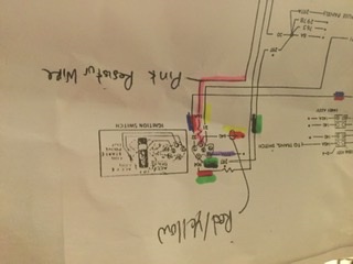
I have the pink resistor wire inline and need to get 12 volts to the coil.
I need to measure the voltage at the + coil, I took some measurements today
for some reason with the Key in the on position(car I am still getting 12.5 volts at the coil.
When I ran the car and checked the voltage on the + side of the coil I was getting 24-26 volts, not sure what is going on
Any suggestions
The new pentronix unit requires 12 volts.
The car runs (I just installed the rebuilt 390), but is hesitating when I give it gas. Not sure if this is my issue
Double the setting you used on your meter, It is impossible to have double the voltage without running it through an amplifier of some sort. With the pink restor wire you should have about 5 to 6 volts with the ignition switch in the run position.
One peculiar thing about ohms law is that with no load you can’t see voltage drop in a circuit. That means you will measure 12 volts until the points or the Pertronix grounds the coil completing the circuit.
You need to set your meter to dc voltage. My guess is that you are getting high readings because the meter is interpreted the pulse through the circuit as a square wave. Meters vary.
All you need to do is run a new wire from the key switch out to the Pertronix red wire. You need to tap into the pink wire at the switch. Leave the coil hooked up exactly as is
Thank you I will run a new wire from ignition switch, I did talk to pertronix, and from the wiring diagram I had, he determined 12 volts from the “c” position on the ignition switch.
My Osborn wiring manual does not have the wiring for the tach
I am positive I had my meter DC volts, because I measured the battery at 12.7 volts
That is why I can not figure out why the + coil was at 24 or so volts
I will double check this and let you know what I find.
Could this problem cause hesitation when accelerating
There is no Ford/Lincoln documentation or schematics for under-dash wiring for tach dashes anywhere in the public domain for Mustangs or Cougars. In fact, those years are about the worst for wiring documentation as Ford’s schematics have wires go into a single “line” and exit, making it very difficult to trace individual wires. Not one of their better ideas.
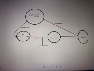
I talked to Pertronix today and they told me to wire the car per the attached diagram.
I ran a wire from the “C” position of the ignition switch, tapped into the red/yellow wire to the positive of the PENTRONIX unit,
And kept the existing wire running to the+ of the coil.
So I ran out of time, but it might be running better, BUT, I am still getting 24 volts to the + of the coil,
Attached picture
wiring diagram for switch
Pertronix wiring diagram
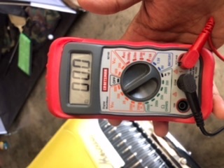
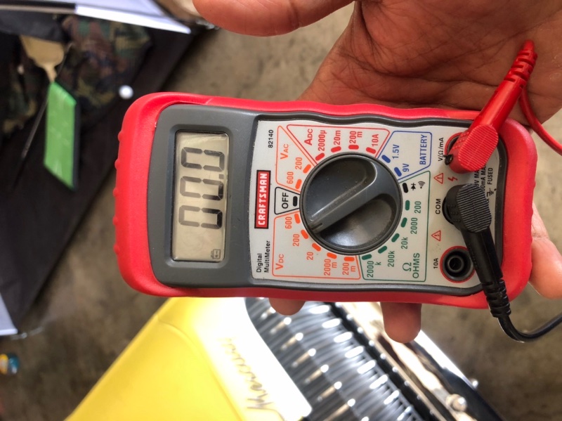
volt meter setting
I was not able to see volts to the + of the coil with the factory wiring
Could I have a problem with the voltage regulator
I will try to trace the factory wiring tomorrow
I also have a 68 XR7 and I’m planning to do this conversion next weekend. My understanding is you can run a splitter between the connectors at the tach/resistor connection and then run that wire directly to the pertronix red wire.
My understanding is you need the 12 volt source from a wire not in series or in the same loop as the PINK resistor.
There is a good restomod, I think it is episode 240 that goes over this and what voltage you should check. My issue that I am having after rewireing ( and before I modified the wiring) is when the car is running I am getting 24 volts at the + of the coil.
From that video, key on engine off; it should be 6 volts because of PINK resistor wire. I am getting 12 volts with engine off, and 24 volts when the car is running (30 or so volts on the negative side of the coil )
We need to see an larger picture of your DVM; it is too small to make out what your settings are. I can speculate as to what you’re seeing, but we also need to know exactly where your probes are touching when you see 24V.
I was checking from the negative e battery to the positive of the coil
When I measured the battery with the multimeter( same setting) the battery was at 12.7 volts
Today I doubled cheddar the wire voltage to the tach with the key on (it was 12v).
Than after the tach before the resistance wire (12v)
ThN I priced the pink resistor wire, about 2 inches in and got 12v.
Should this be 6v
You won’t see the voltage drop until the circuit is under load. That only occurs when the circuit is completed by the closing of the points or the Pertronix switching the black wire to ground. You can briefly connect the negative pot of the coil to ground but don’t leave it, the coil can overheat. Why not just hook it up properly? Run a new wire from the pink with green stripe wire st the back of the key switch to the red wire on the Pertronix.
I’ve used pedaptors from the Rocketman to power the Pertronix modules in both of the Cougs I have owned. Both ran beautifully and never gave me one problem. Affordable and easy to install. Highly recommend…