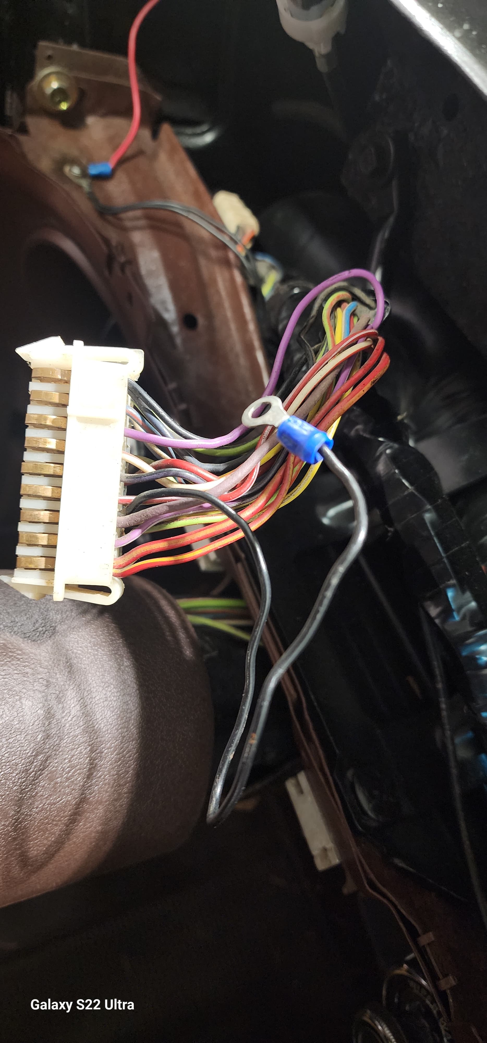
70’ XR7 gauge cluster wiring connector black wire termination on pin 12. Someone was in here long before me and has put some kind of a butt connector on the black wire. I took the cluster out two and a half years ago, and I cannot for the life of me remember what I took it off of, or if it was even connected to anything. When I searched the electrical diagram PDF, it appears it is wire number 48 (black) but shows no termination point. Does anyone know where this wire terminated originally. Thanks


1 Like
Looks like a ground. Maybe for a section of the instrument panel. Likely attaches to the dash frame with a self-tapping screw.
1 Like
Pin 12 also connects to a violet resistance wire (#30). It powers the Instrument Voltage Regulator (IVR) that generates pulsed 5V for the gauges. That black wire (#48) that also connects to pin 12 is called “BLIND CIRCUIT” on the standard Cougar schematic. It would carry that same switched voltage that goes to the IVR (12V minus the drop across the resistance wire). I have no idea what it is for, but don’t ground it.
Its definitely not a ground because the violet wire in the same pin is a powered resistor wire. I thought so, too originally, and luckily I did not fry anything. It did mess up the entire cluster, though. None of the gages worked when it was connected.
1 Like
I have an XR7, and it is a violet colored wire in my harness.
1 Like
Yeah, my bad, It is violet and I corrected that in my post. You probably didn’t do any damage for a short time because the violet resistance wire just heated up.
1 Like
Yes, no damage.I thought originally it was a ground. When I grounded it , none of the gauges worked anymore. I have searched all my pictures when I took the car apart and unfortunately ,that wire shows up on none of them. Someone before me put the connector on it, and it looks like it went to a place that either used a screw or a nut to hold it on.
1 Like
Yes, you would short out the voltage supply to the IVR with it grounded, so no gauges. I can’t imagine what “BLIND CIRUIT” was intended for, or what your PO had hooked to it, because that line would pulse between 12V when the IVR opens, and something less than 12V when the IVR closes. Maybe somebody else on here knows…
1 Like
I really appreciate you putting your two cents in. Someone may have the answer and we will all learn a little something from it. I have another harness, its not an XR7 but ill take a look after dinner and see if it’s on there.
1 Like
Schematic shows the same two wires on Pin 3 of the standard Cougar harness. It will be interesting to see how the black wire is terminated on that one.
1 Like
Excellent , hopefully , I haven’t butchered it and removed that wire. I’ve used that harness a lot for repairs on mine. Mine was so corroded from sitting for years and I needed to steal the fuse box and other related wiring to patch into my XR7
1 Like
That black wire is there for structural integrity at the dash cluster pin. The violet resistor wire is a single strand, about 28 gauge, and can’t be crimped by itself. So…Ford added an extra wire that doesn’t go anywhere so the pin could be crimped and maintain continuity with the resistor wire.
3 Likes
Thank you Midlife! I figured you would know, and that makes perfect sense!
On a related note, I need to replace my fuse link from the solenoid to the main harness on my 70. Can I use a crimped butt connector to the old black fuse link segment still in the harness?
1 Like
Awesome much appreciated and it makes perfect sense. I will cap it off so It cannot short to anything. As I was saying somebody will know and we will all learn something today. Thanks again
1 Like
Ah Ha! I was wondering about “blind circuit” when I went through mine; now I know! Thanks!
2 Likes
Yes, but make sure that the 14 gauge fusible link is a total of 9 inches: no more, no less!
2 Likes
Great to know - thank you!
1 Like