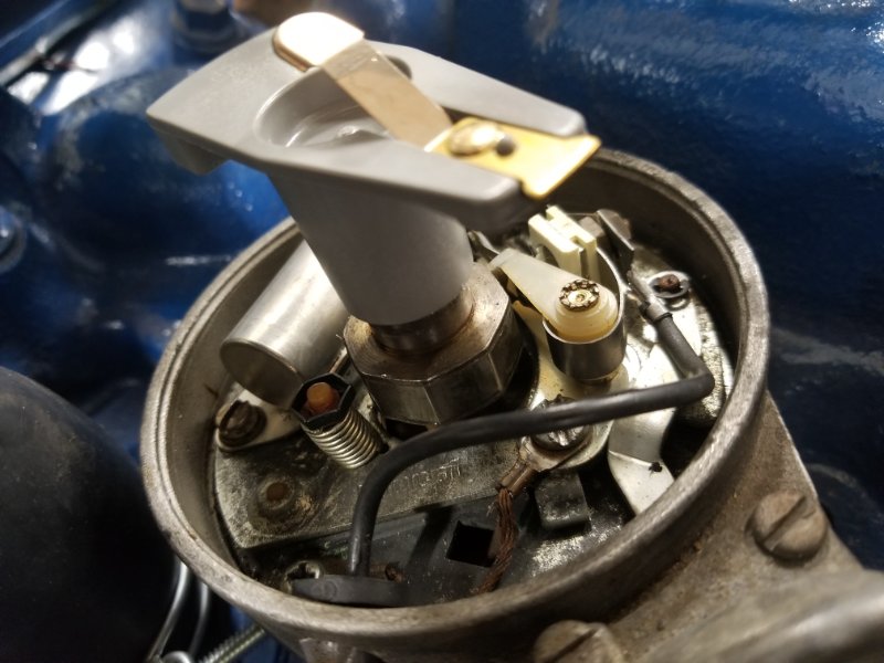
I’m attempting to get the 70 XR7 running for the first time since rebuild. It has the 351C 2V. I have new gauge feed and alternator harnesses, new dist cap, rotor, plugs, wires, relay, voltage regulator, starter, alternator, condenser and coil. The only thing I had not replaced was the points because they looked brand new. We gapped the points at .17 per the maintenance manual. I have 12v to the coil, the engine turns and I have spark at the points. The voltage regulator gets hot after cranking for a while but I assumed this was normal, due to the cranking without starting. The problem is, there is no spark getting to the plugs. It’s almost as if the rotor is not transferring the voltage to the plugs but it is a new part. The rotor is turning. Does anyone have any ideas?
Royce, I know it has 12v at the coil with the key on. I’ll check it this afternoon to see what it has while cranking. If it does not have 12v while cranking, could this cause no spark to the spark plug or a weak spark? Thanks
What do you mean by having a spark at the points? Are you getting a spark from the coil output wire to ground but no spark from any plug wire to ground?
If it doesn’t have 12 volts at the coil while cranking it won’t start ever. Likely a disconnected wire would cause it, but first you need to verify what the problem is. Once you know what the problem is we can figure out how to fix it.
The other requirement is ground at the - side of the coil while cranking. While cranking a volt meter with the - wire can be connected to the - side of the coil, with the + wire from the volt meter connected to the + side of the battery. You should “see” the points opening and closing on the volt meter while cranking if all is proper.
Correct, there is a strong spark at the points gap when checking it without the cap on. There is no noticeable spark at the coil output wire nor is there a spark at the plug wire when I ground it out.
The battery is slightly down so I put it on a slow charger. It’s charging above 13v. With the key on, there is 6.73v to the coil. When we crank it, it goes to 9.45 max. So I stand corrected. it does not have 12v during start. However, the fact that it is a lower voltage with key in run and higher voltage with key in crank, makes me think the factory wiring is doing what it is supposed to do.
My buddy and I figured out the no spark problem and it is no a common one, at least i don’t think. Actually it was a couple different things. The plate in the distributor that runs the vacuum advance was tightened down but it must have not been seated properly. It shifted, causing the points gap to close after we set the gap. We set the gap several times and it kept closing. We unscrewed the plate, moved it around some and then tightened up the screws. It doesn’t have slop anymore. We also put the old condenser back in because the new one either stopped working or never did work. There are still electrical issues however. The only gauge that works is th amp gauge. I’ll probably be posting a request for help on this issue in a few days if i can’t figure it out. Thank you all for your help on this problem
“The only gauge that works is the amp gauge.” This points to the only thing they have in common, the Instrument Voltage Regulator. Unplug the temp sender under the hood. Hook up a test light to the wire you just disconnected. With the key in the run or accessory position, the test light should flash. No flash means no output from the regulator.
Sort of. A DVM will not like it very well, but it will show a rapidly changing read out. An older analog meter will show the needle sweeping back and forth.
A common problem for 69/70 dash clusters when the gauges (not the ammeter) don’t register is due to a slight misalignment of the gauges when a new circuit card is installed. The gauges have some slop to them in the dash cluster and the posts can contact the metal housing on the back side, shorting the circuitry for all the gauges (power for non-ammeter gauges are all tied together). You can’t see the contact because it is hidden under an insulating pad, the locking nuts and the circuit card. Usually, one removes an oil/water/fuel sending unit wire and briefly ground it with the key in ACC to test if the gauge circuitry is correct: the gauge should peg high. If it doesn’t, the issue described above is typically the cause (although the constant voltage regulator can also fail).
To test if your gauges are shorting against the dash cluster, remove the dash cluster and measure with a digital volt-ohm meter the resistance between any non-ammeter post and the metal housing. If there is a short, the reading will either be 0-1 ohm or 14 ohms. If no short, the reading will be in the kilo-ohm or higher range. Now the problem is to find the shorting gauge…