I wanted to share my experiences upgrading my original Alternator to a Ford 3G style 95 Amp unit.
I used PA Performance as they sell an Alternator that they claim fits a 1969 Mustang 351 and also sell an external regulator (not truly needed as the Alternator supplied is internally regulated) which allows you to keep the existing wiring. When I do a mod I usually try to make it look as stock as possible (when possible) so I liked the prospect of keeping original wiring. Of course with a more powerful alternator additional thicker wires will be required for power and ground from the alt to the battery.
It didn’t go (and it’s still a work in progress) as easily as I had hoped, but they never do. Here is my experiences so far…
Let me start from the beginning…
Prior to trying the PA 95 Amp Alt that is advertised as fitting a 1969 351W (Mustang) I ordered and tried to install a 130 Amp 3G Tuf-Stuff (7771) but it had two issues, the first one was the alternator housing interfered with the adjustment travel which would require several modifications, including the alt itself. The second one was the hole that is threaded in a 1G alt is not threaded. This would make adjusting the tension a real PITA, or I would have to weld on a nut (or something to that affect).
The PA alt does have a threaded hole (the bolt is included, which is a good thing since the stock bolt does not fit it) and “fits” a 351, so I went down that path. As you will see in my next posts the fit has exactly the same issue as the 130 Amp 3G alt, there is interference in the path as you pivot the alternator around the longer upper bolt.
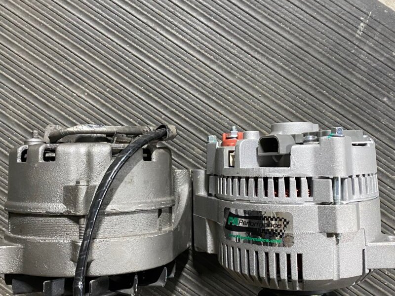
Below is a picture of the original alt and the new PA alt side by side, they look pretty similar in size, but the PA 3G is slightly deeper and here is where the interference comes in. Those 3 bolts that hold the alt together will be haunting us soon enough! You can see how the 1G has the bolt heads recessed into the body while the 3G has them protruding out the back!
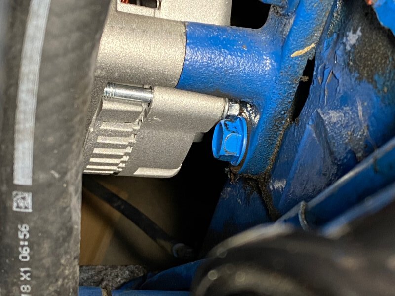
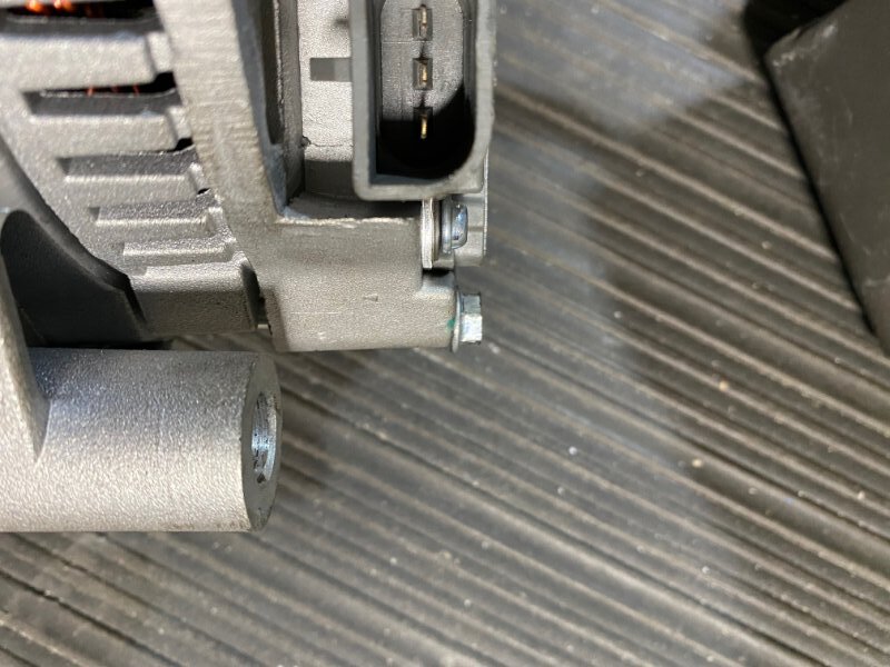
Here is the new 3G alt installed into the car and you can see the interference with the bolt on the alt with the bolt on the alt mounting bracket (the right smaller bolt). In the picture it looks like the lower bolt. You can see this isn’t just a 1/8 of an inch worth of interference. It is more like a 1/2 inch maybe a little more and will require the bracket modifications I was originally unwilling to do for the 130 amp Tuf-Stuff unit. But I wasn’t willing to wait anymore for a different alt to be ordered, So I went for it…
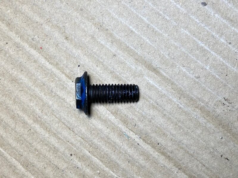
My plan of attack was to first shave off ~1/4 inch from the bolt head of the alt mounting bolt. I wanted to take off as much as I could without compromising the bolt and the ability of getting a wrench on it to tighten and loosen it. Not being a metallurgist, I can’t talk to the strength compromise, but I was still able to get a wrench on it to get it in and out. This turned out to be inadequate and required additional effort.
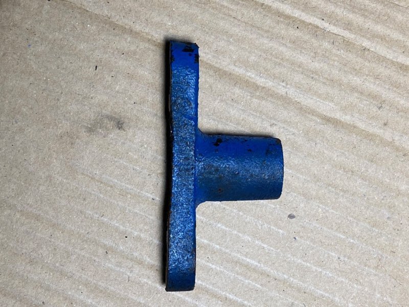
I now realized I had to thin the mounting bracket. Again I needed to take off as much as I could without compromising the integrity of the bracket. Fingers crossed…
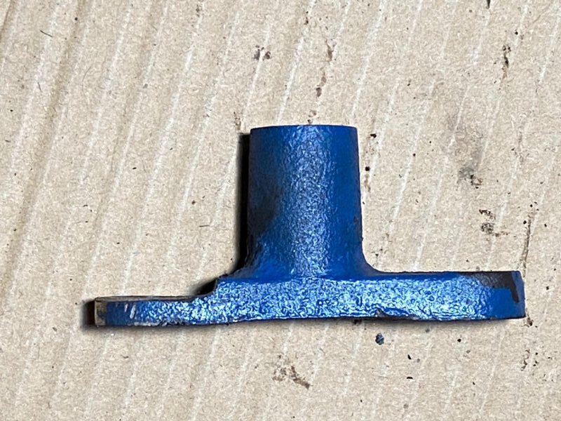
Modified Bracket… This is not the final cut, I did do a bit more “leveling” with my belt sander.
This trimming is on the smaller hole in the bracket (for some reason one hole is larger than the other).
The last piece of the modification was the alternator itself, I needed to take off some of the bolt that was causing the interference.
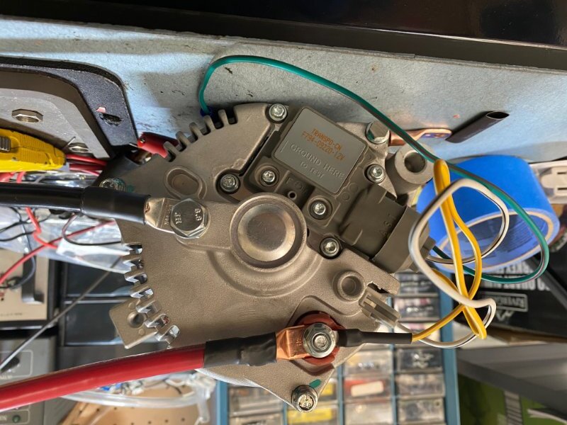
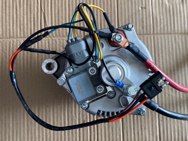
I also needed to “Index” the alternator to orient the power connection to be in an open area, the original indexing had the power connection nearly shorting out to the engine block.
Here is the indexing…The modified bolt is in the upper right in this picture (the green wire is just touching it). I’m adding a new beefy ground to go to the engine block (same spot the battery is grounded). The wires are #4 battery cables with me custom cutting and fitting the lugs.
P.S. The Grounding Bolt (in the Alternator) is a metric M8-1.25, I used a 20mm length bolt, you could probably get away with a 15mm length.
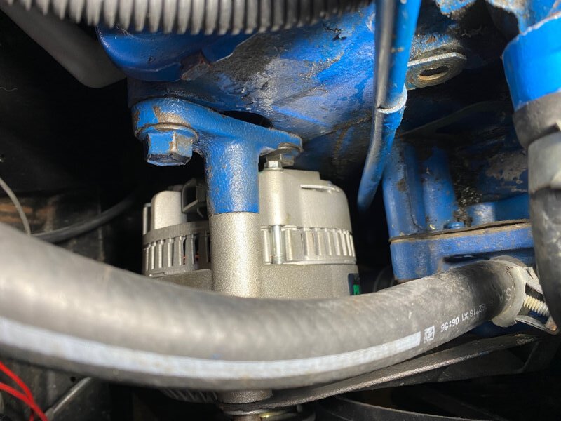
So here it is installed and it now can swing past this point and I can now bolt it in and tension the belt, as required.
The wiring will be next on the effort. So stay tuned!
I have higher hopes for the wiring as the research I did on that and the PA description of what their doing seems to jive (fingers crossed)!
One quick point, talking to the PA support people I mentioned that I tried a 130 amp alt and it had the same mounting issue.
He claimed that It was a good move that I went with their 95 amp alt and not the 130 amp alt as I have a single V-Belt and they claim that many people have reported belt noise and slippage with poor alt output because the single V-belt couldn’t engage the 130 amp alt well enough.
It makes sense, but you never know if your just getting a sales pitch, but his point did make sense to me.
Now on to the electrical, this did go much better…
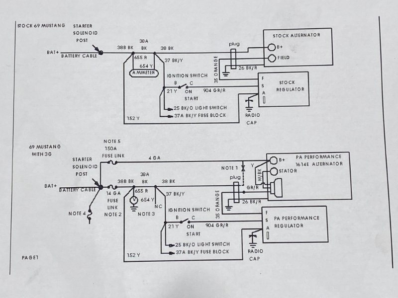
Here is the wiring diagram I followed for the PA alt and Regulator. The instructions that come with the items does not completely jive with this diagram, but I followed the diagram and everything ended up working. This diagram matched what I had for schematics and the wire numbers and colors that I have in my car.
Here is the new Alt with the complete wiring. It includes the existing harness and the two new high power (#4) wires (+12 and Ground).
The directions that come with the unit say not to connect the Blk/Red wire to ground as it has some signal on it. Reviewing the schematic and the prior diagram indicated to me that this should be connected to ground, as it was in the original wiring harness. The Orange wire goes to the alt Green/Red wire.
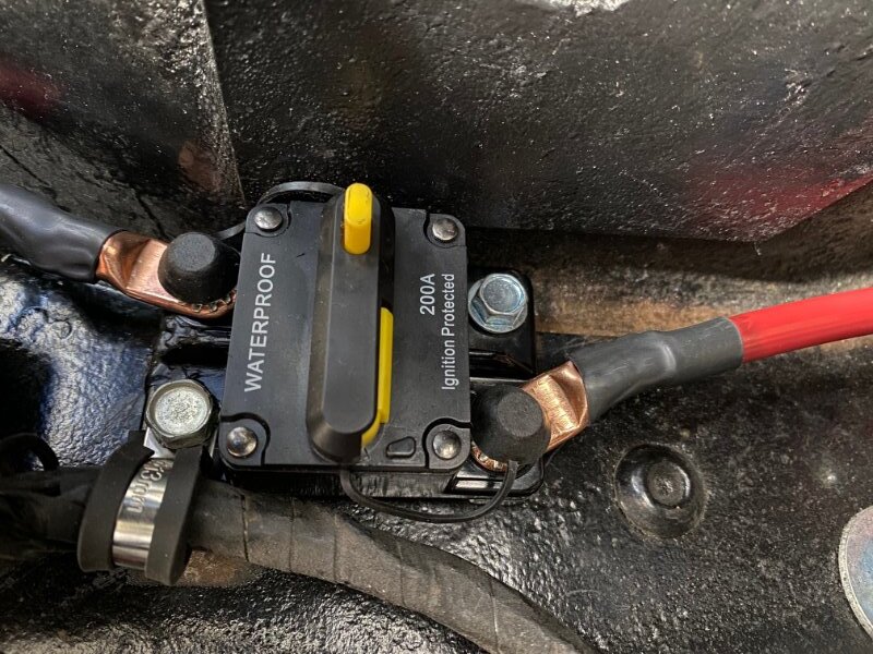
Here is a picture of the 200 amp circuit breaker (I originally was using a 130 amp alt so that’s why the breaker is 200, if I started from scratch with a 95 amp alt I would have used a 150 amp breaker).
Nice write up. Thanks for posting all this!
I have the 95 amp alt from pa performance and their dummy external regulator kit to install on my ‘69 as well. I am just waiting on my modified dash amp meter conversion to volt meter to come back from rocketman so I can install everything. From what I understand, the new alt does not play nice with the original amp meter.
Daryl,
I also heard that the charge meter would not be accurate with this mod. This setup leaves the original wire, so current flow will still be read by the dash meter, it just won’t be as accurate as it originally was.
With that said, I left the amp meter in and it reads very slightly more toward the right. I can’t remember that meter ever reading anything but 0. I’m not overly concerned about the inaccuracy and my EFI system has a battery digital readout. But changing over to a volt meter makes sense to me.
Good Luck,
Jay
I have now been running this new Alt setup for 2 day’s (~20 miles of driving) and I have the belt pretty tight.
I get some initial belt squeal when I first start the engine. On day one it lasted ~5 seconds, on day 2 the squeal lasted about 20 seconds before subsiding.
I imagine the belt will require tightening as it stretches (it is new). The belt is a Gates and they advertise they get “Grippier” as they heat up, and I think that might be saving my butt!
I now whole heartily agree with the PA tech, the 130 amp alternator would have been a real screamer and might very well have not worked with a single v-belt system.
I think I mentioned this before, you have to put about 50% more power into the alternator than it can put out. This is one of the main reasons late model cars run serpentine belts. It allows for a smaller pulley that turns faster and has a lot more surface area for belt traction. From a practical stand point, if you can delay electrical accessories (electric cooling fan, AC condensor fan, HVAC blower fan, stereo amps, etc) so they don’t fire up right when it starts, that will help. Also, check for any parasitic loss that is pulling the battery charge down. If you have EFI, turn the key to on, let the fuel pump run til it makes full pressure then turn the key to start.
All good points, thank you.
I always let the fuel pump finish it’s prime, I believe the Holley EFI instructions tell you to wait 5 seconds after turning the ignition to “On” before cranking (to allow for the fuel pump to finish it’s prime to get the fuel into the TB for a quicker start).
I never have any HVAC running on start up, or the radio on, and I don’t have an electric fan.
I tightened the alternator belt again and the squeal lasted just a second or 2. I also checked the pulley alignment using a laser (not designed for the task) and as far as I could tell the alt pulley is aligned pretty well. I did have to adjust the A/C compressor alignment, that was not quite correct.
Could you please elaborate on your parasitic current comment? Are you talking about checking what the current draw is on the battery when the ignition is in the “on” position with the engine not running?
Thx,
Jay