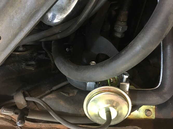
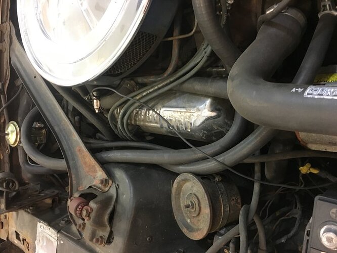
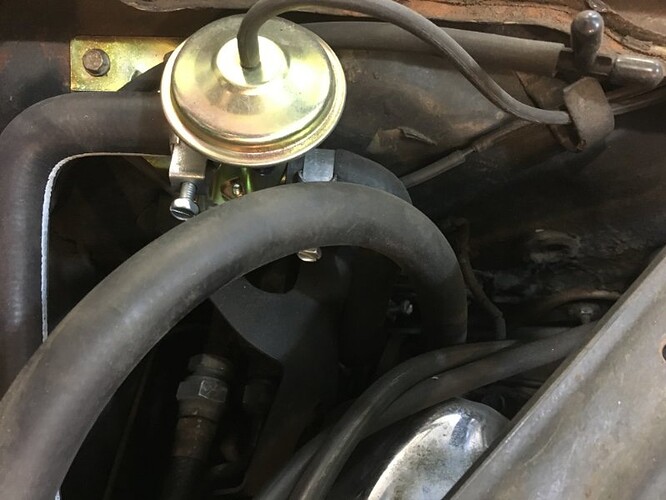
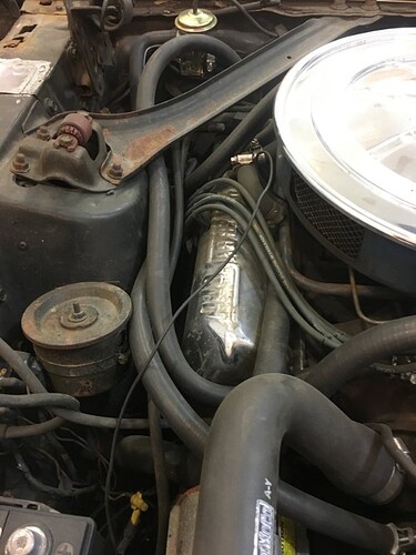
Looked a long time this afternoon, trying to find info on the correct location of the heater hose that runs from DS heater core outlet back to water pump on an early 67 390 car with AC. Don’t seem to find it in blue manual either in the heating section, or the AC section. I think the closest I found (it’s all a blur I’ve looked at so many posts) was Jeff Speegle saying he has seen it two ways, running up along the valve cover where intake attaches to head, and routed out with the other hose that comes back to the intake from the control valve. In either case is there any straps/loops that hold the hose in place? I know the small block has a spring “saddle” that mounts by the carb.
Thanks,
David
My 67 is a later built May 1967 GT 390 AC CA emissions. On my car the DS Heater core outlet goes directly to the Intake manifold. The PS Inlet goes to the “Z” shaped hose to the control valve. Then to the water pump. This way when the AC is turned on it shuts off the flow of coolant thru the heater core. That way your not trying to heat & cool at the same time ![]() I have no brackets holding the hoses other then one to hold the vacuum line to the control valve. I assume at one time their was most likely a strap on the export brace holding the heater hoses. But, don’t know that for sure.
I have no brackets holding the hoses other then one to hold the vacuum line to the control valve. I assume at one time their was most likely a strap on the export brace holding the heater hoses. But, don’t know that for sure.
Thanks kindly guys! Think that is the route I will go. Not going for concourse anyway. Two things I notice in the pics. 1) Don’t look like you have your AC hooked up as there is that T in the line that looks like the vac tank supply hose, and it is capped off. You probably have the tank outside of the inner fender. Anyway, wondering where that supply hose is suppose to route. I am guessing through that loop on the firewall, turn it and bring it down the right side of intake, and connect to the vac tree on the ps front corner of intake that the pcv tube fastens to?
2) Notice you have the shield in place they used to protect blower and or AC evaporator tubes in place. Didn’t think that was possible to have in place with the AC lines hooked up?
Thanks again!
David
I re-oriented the pics for more pleasurable viewing. Been battling a cold the last few days so upside down and backward looks normal to me ![]()
I got the Cougar in August and at that point it was pretty much untouched original except for a repaint and some maintenance items. The shield is original and is in place with the AC lines. It had a leaking heater core and that area was taken apart to replace the heater core and the control valve was leaking as well. if I remember correctly the line that is capped off in the picture is the vacuum supply line to the reservoir can for the tilt steering wheel.
I have had 6 390 Cougar and Mustangs over the years with A/C and the heater hoses have always been reverse of what the above pictures show. They were like that when I bought them so I didn’t change them. The hose from the DS outlet has a formed bend in it so not to crimp, it runs along the top of the valve cover under the PCV pipe.
Intake hose to water valve, DS outlet to water pump. Maybe functionally it doesn’t matter.
“The hose from the DS outlet has a formed bend in it so not to crimp, it runs along the top of the valve cover under the PCV pipe.”
So have all 6 of your cars had that hose in that same spot? Like I said I think it was J Speegle that said he has seen the routing both ways with that hose over the valve cover, and also next to the shock tower. I would guess with the cars with smog there wouldn’t be room over the valve cover?
Will have to see if I can find a flow diagram for an AC car.
Were all 6 of yours 67 with AC?
David
and look at hoses 18472-11 or 24 B. One end of one hose bends to the water valve the other end of the other hose bends up from the DS outlet. My cars were both 67/68. I’ll look for a picture.
The 67 chassis assembly manual shows the hoses routed even with the thermactor system installed. 390 max vacuum/ hoses diagram. The assembly manuals are a worthwhile investment.
I don’t have the specific chassis one, and at this point don’t intend to buy it. Maybe someday if I find a used one it might be nice to have to see what I all did wrong ![]() I did look in the big blue factory service manual, and it shows with arrows in every engine scenario including straight 6 (if I recall it right as I type) that water flows from the manifold to the heater core with it flowing from heater core back to the water pump, which makes sense that the water pump is ‘suctioning’ the water back. I have not found a specific diagram in that book as of yet that shows it with AC valve, but want to thumb through it again.
I did look in the big blue factory service manual, and it shows with arrows in every engine scenario including straight 6 (if I recall it right as I type) that water flows from the manifold to the heater core with it flowing from heater core back to the water pump, which makes sense that the water pump is ‘suctioning’ the water back. I have not found a specific diagram in that book as of yet that shows it with AC valve, but want to thumb through it again.
So I would think that it makes sense that the manifold line would go to the water valve flowing into the core, with the other line coming out to the water pump.


