Ok, so at least the turn signal problem is solved then, didn’t even notice the adapter portion with my wires when I was messing with them. I will check on these tonight or tomorrow at some point.as far as number one is concerned if I follow the wires up to the main harness, what does the extension harness look like? is it just a connector with the same two color wires as the brake switch coming out of it or does it look different? as far as #2 is concerned is the original 3 pin black connector housing and red wire. are you talking about the red wire that looks like its going behind the steering column/brake pedal? is that where that 3 pin connector housing would be or is it somewhere hidden beneath the wires in my pictures. just trying to make sure I trace the right thing when I go to check.
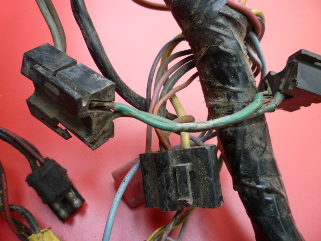
Here is a picture of the 1968 disc brake light extension harness. This particular example is frayed on the end to the right - a typical failure.
Tom -
The K5 indicator relay connector may be hidden in your picture. It should have orange/green, brown, and orange/black wires.

Hi I’m mike and I’m 25 and just restored a 67 cougar and some reason my turn signals will not work at all. Not even my 4 ways, brake lights work when they want to the car is restored to the ground but the wires I have 49,000 miles on it and can’t even drive it cause I’m scared someone will rear end me and all my time and money is out the window so if someone can please help I would be great full thank you
Vic,
So upon further review I have found the following:
#1 the nylon bushings were not present on the brake light switch
#2 the power disc brake extension harness is not present
#3 the green/red wire was hot the entire time even before I started pressing the brake pedal, the green/white wire was only hot when the pedal was on the floor, but it was not intermittent, every time I put my foot to the floor it was on and the brake lights were on
#4 the other relay was present that you asked me to find with only the three correct wires coming out of it, may have just been the way I was holding the camera
#5 following all of the wires I saw no fraying other than that of the green/white wire on the crimp connectorat the brake switch.
So based off of all of this is my issue maybe just the bushings and the crimp connectors?
I remember shooting those under the dash shots… what a pain in the neck back and ass.
I have a purple and green wire on a L shaped connector under the dash near the fusees on my 67 and it’s same color wires that go to the turn signal lights in dash don’t know where it goes. Does anyone know where this might go? I have no turn signals all a sudden
So next thing in the Saga with may car. I replaced the turn signal box with a 1968 box, had to rewire a lot because at some point someone rigged the system to work with a 67 and jumped two of the bulbs together so it didn’t work too well with a 1968. they are working perfectly now.
the unfortunate thing is that the brake lights still don’t work. I replaced the brake light switch again, this time with the bushings attached to the pushrod, as well as the pedal.and i also replaced the crimp connectors with the factory connector.since the crimp connector was jammed on the brake light switch and broke. this actually made things worse, and now i have no brake lights at all not even intermittent. I tested the contacts multiple times on each of them, and from what i saw the green/red wire is always hot like it should be, and the blue/white wire, which attaches to the bottom, never comes on. i even tested taking that wire off and putting my test light directly on the contact and it never lit up.
If you have any insight into this please help. Ive checked everything and replaced everything i can think of at this point and I’m not sure what else could be wrong. It seems like the switch is never being activated at this point, so does that mean it could be the brake booster? or am i overlooking some other detail?
I am having a heck of a time with Heather’s 69 XR-7 convertible with tilt.
She had been having turn signal issues that I decided to jump into with both feet, along with some other issues she was complaining about (sorry, but it is going to take more help than what would be available from this forum to deal with her complaints about me). I got the tilt turn signal switch I was saving for another project to use on her car. I took out the driver seat (trust me this is most helpful on your back, etc.) and got under the dash to disconnect the plug between the switch and the car harness and discovered that a previous owner/mechanic had cut wires to both sides of the plug to wire into the main harness, as well as just past the old switch and under the wire cover on the bottom side of the column. I wanted it to be done correctly, so I immediately consulted the shop manuals, electrical diagrams, and even some Devine intervention. Not much help from the manuals and diagrams, still not sure about the help from a higher level.
I am very surprised that there is no plug and wire diagram on this, other than one that is generic for Mustang and Cougar (and other models).
Does the tilt option change any of the wiring positions or wiring colours?
Does anyone have a switch end diagram with wire colours they can share to this thread?
I appreciate any help I can get.
Scott -
There is a diagram on my website for both the 1967 and 1968 Cougar turn signal switch pins (both sides). The pin orientation for the 1969 Cougar tilt switch is the same as the 1968. A 1969 Cougar standard column switch is similar but doesn’t have the red wire, so that position is empty.
http://www.thuntek.net/cougars_unlimited/1967-68_TS_Connectors.PDF
I stock both sides of the half-moon turn signal switch white connectors and pins.
Re: No brake lights
Tom -
Is the contact plate on the switch still flat? I have had switches where the contact plate was deformed (concave) so that the rod movement did not actuate it. My solution was to add another contact plate removed from an old switch to take up the slack.
Also make sure that the booster rod is the correct part.
Thanks for posting this. It looks like the 69 wiring colours are different from the 68. I have a cut plug I just acquired (vehicle harness to turn signal plug) that I am going to use as reference to fix Heather’s 69. I will let you know how it goes. Do you want me to send you the wire colour sequence? Maybe you can create a 69 version of the turn signal connector file.
By the way, I clicked on the link to the BARGANSPOT site and noticed all the wiring harness stuff you do (which I didn’t know that you did until today). Very nice.
Re: 1969 Cougar turn signal switch connector diagram
Scott -
The 1969 turn signal switch side connector wires are the same as the 1968 Cougar with the exception noted above.
Note: the diagram shows the connector wire colors from the pin side.
I’ll update the diagram to show the wire color assignments for the car harness side, which is different for the 1969 & up Cougars.
I matched up the same colour wires on both sides based on the car harness plug I acquired. Tests so far show that they are working, except flashing very quickly (most likely need new flasher canisters).
I hope I’m not going to catch the car on fire.
I have a '70 Cougar, and the issue is with the park lamps on. When they are on, the turn signals do not work. Is it getting power from the from the headlamp switch, or the relay can under the dash is going bad? Or is there another issue I need to follow? i have replaced the turn signal switch due to other issues that are resolved.
I have cleaned up the battery contacts, and it seems to have worked. I don’t pretend to understand it, but it works. All of my lights and turn signals work in all positions. So try cleaning your battery contacts in addition to your regular diagnostics.
Vic,
The Contact Plate Is still flat and on top of it the rod is the stock one that came with the original midland ross brake booster that is on my car, has not been changed in some time the only thing thats been changed is the master cylinder… The car sat from 91-2014 and we are still using the same booster. is it possible that maybe the booster could be bad? how can i tell? i don’t have to put my foot to the floor to stop, and it has pretty decent stopping power at least to me. I’m just out of ideas… and unfortunately i do not have another plate to put back on it.
Replaced both flasher cans with new style solid state from the local auto parts store, but it did not solve the quick flashing of the turn signals or the emergency lights.
Anyone have a suggestion to fix this?
Scott
I read your post and have some questions and suggestions to troublehoot the issue.
When you say flasing very quickly. are the bulbs sequencing or is only the inner bulb flashing?
Are you using a stock sequencer or a newer solid state designed unit?
Are you using LED bulbs in the tailigts, front parking lamps and/or side markers?
When did the issue start to occur? Last changed item, first to be reverted/tested is my motto.
The components that affect the turn signal operations are as follows:
- Charging system
- Emergency flasher
- Turn signal flasher
- Brake light switch
- Turn signal switch
- Sequencer in the trunk
- bulbs in the taillights, parking lamps and side marker lamps
Check your charging system, make sure the alternator is putting out 13.7 to 14.5 volts. Also check the battery condition and just as important the ground wires. Also make sure the ground wire to/from the sequencer in the trunk is clean and tight. It is very important to run all of your turn signal tests with the engine running.
Grounds, grounds grounds!!! Make sure the sequencers, bulbs and all electriconics are properly grounded. If a ground wire is not clean and attached properly, the power will search for a path of least resistance and ground through to another component with unintended results. For example, if a dual filament bulb is not grounded properly, the power will flow from one filament into the other and from there it will go to the path of least resistance.
I highly recommend for a first step in troublhooting especially if you are using a oem sequencer, is to use the appropriate incandescent bulbs throughout. Remember the OEM system was designed for the amperage draw for these bulbs.
Are you using LEDs in any of the taillights, rear marker lamps or front turn signal lamps? The original system was designed for use with incadescent bulbs not LEDs although the new solid state reproductions will work with LEDs BUT needs either an incadescent bulb in the front turn signal or a load resistor.
LEDs can have internal issues and have caused short circuits with unintended behaviors as JETEXAS posts https://cccforum.discoursehosting.net/t/1967-tail-light-troubles/8052/1 about his issue using LEDs.
Front Marker housings recently replaced? If I remember correctly, the Mustang housings are wired differently than those of the Cougars and again will wreak havoc with the system.
Good Luck
Coach Jack
Thanks for getting back to me Coach Jack.
They do sequence, but very quickly. Basically by the time it gets to the farthest outboard bulb and it starts to light, the system is off and then restarts the sequence
It appears to be the original sequencer in the trunk, no LEDs (although I was thinking of switching it all over for her).The front turn signal housings and all markers are original (bulbs changed with new incandescent when they have burned out She was having issues previous to my changing of the tilt away turn signal switch with the quick flash, but I’m not sure how long as her car was back burnered for some time due to us taking my G to Carlisle and Dearborn this year.
Most of my testing has been with the engine off, but I will start to look into some of your other suggestions.
Where is the ground wire for the sequencer in the trunk? I did find a plug with nothing plugged into it, but there was a ground on it that was not attached. This wire runs right beside the main harness coming into the trunk area.
Also, just in case it matters, her 69 XR-7 is a convertible.
Scott Ferguson wrote: “Replaced both flasher cans with new style solid state from the local auto parts store, but it did not solve the quick flashing of the turn signals or the emergency lights.
Anyone have a suggestion to fix this?”
Scott -
The auto parts store flashers are designed to flash from 60 - 120 flashes per minute, with a 50% “ON” duty cycle and typically run at about 90 flashes per minute. This means that the total “ON” time is only .33 seconds. This flash rate/ON time is too short for sequential lights because an 1157 bulb takes about .2 sec to turn on or about .6 sec total for three bulbs.
The original 1969-73 Cougar flasher (marked 4-lamp sequential trigger) was designed to operate at a slower rate with a longer “ON” time.
I developed a replacement flasher, D0WY-13350-AR, that runs at a slower rate and has a 70% “ON” time similar to the Ford flasher. It should be used for both the turn signal and emergency flasher on the 1969-73 Cougars.
http://www.ebay.com/itm/C6-1969-1970-1971-1972-1973-Mercury-Cougar-Sequencer-Flasher-Can-Ford-/250970103075?vxp=mtr&hash=item3a6efbdd23
Note: I’ve discovered that on many Ford vehicles, the emergency flasher plug is wired backwards. The red/white wire is swapped with the white/red wire. This “feature” doesn’t affect the original electro-mechanical flashers but electronic flashers are polarity sensitive. The individual wire leads on the D0WY-13350-AR flasher allow the pins to be swapped if necessary.