68 XR-7 Restomod Build

Thanks man!

Honestly, it’s mostly because I have to keep ahead of the spiders, lol. The shop area is behind a dairy (we live on a county island in Glendale)…and if I don’t clean out the webs on a daily basis, the thing would be taken over completely within a week. Most of them are harmless daddy long leg looking things…but I finally just this week managed to find and kill a particularly stubborn black widow that had made her home under it. I’ve known she was there for about two months…and its really disconcerting to be working under a car that you know at least one hidden crevice is hiding a painful surprise.

As far as the car goes…I went ahead and bombed (literally) one side black today. It’s going to take a few cycles of sanding and recoating to get the effect I want with paint (which is old, worn black primer over semi shoddy body work). The toughest part is that time blends out the paint marks you inevitably get when you spray something large with a paint can. That’s where wet sanding comes in though…and careful application of filler primer to smooth the deepest existing scratch marks. Hopefully that will smooth it out.

I think in the end it’ll turn out like I’m picturing though. Sort of an old street race project you might find under a tarp in the deepest part of a closed down hot rod shop. The kind of shop that put all of their talents into going fast…with a reputation for stupidly quick cars…not immaculate paint and body.

I just realized I forgot to post up the pictures of the car black. Here they are:

I really do like it. It also makes the wheel wells look a lot better (less contrast on the gap I think). I may end up ok with just bolting on 28" tall tires. Going to finish the rest of it sometime this week.

I also got my strut rod stuff and my tie rod adapter tubes in from Speedway today. They of course sent me two left hand rod ends, when I needed (and ordered) right hand. Sucks, because even the package said RH. Oh well. I did get my tie rod adapters cut down, rewelded, and installed. If I had a mount for the rack and the steering shafts, the car would steer. Hopefully I’ll get to that over the next couple of weeks though.

First I roughly lined everything up so I could get a measurement for the adapter. It looked like I needed 4.5" or so. Now, the inner rod on the Mustang II/Pinto rack is a 9/16-18 RH thread, and the rod ends I’d bought for the steering/bumpsteer were 5/8-18 LH. I looked EVERYWHERE for a 4" piece of swedged tubing with the appropriate threads on either side with no luck. The closest I found was a 7.5" tube from Speedway. They were on sale for $6.99 each (they aren’t going to carry them anymore), so I bought four just in case I ever screw one up.

Basically, I just cut 2.5" out of the center of them, beveled the edges, then clamped them down and welded them up. It turned out though that on the car, 4.5" is just a bit too wide, leaving only about 1/2" inward adjustment (which may actually be fine, depending on where the tires end up when aligned). worst case, there’s 1.5" of thread on the inside of each side of the tube. I can easily grind 1/2" off each end, and still have plenty of thread engagement for safety, while giving myself another inch total of wiggle room.

These are the strut rod ends (they were supposed to be AFCO, and I paid AFCO pricing for them…I’ll be bringing that up tomorrow when I call about the rod ends), along with the 10" lengths of 5/8" swedged tubing. It seems I also miscalculated the length on that somehow (weird, everything else I measured ended up dead nuts!)…but again, I have some wiggle room by grinding down the tubes. Worst case, I can always order a new pair of shorter tubes…they’re not that expensive.

So that’s where we sit now. I’m pretty happy with how it’s coming together, and once I’m done with the front end I’ll be doing the header adjustments, getting the motor mounted permanently, and then probably start on disassembling my shortblock in preparation for enlarging the lifter bores. From there it’s wiring, EFI (I’m actually going back and forth about just putting a quad of single barrel carbs on it this year to get it running, and doing the EFI with next years taxes…guess we’ll see!), putting the shortblock back together, and interior. I’d say I was about halfway done now, except I think the second half is going to be harder than the first, lol.

More updates as they come, of course =p.

That bad boy is coming together really cool. Keep up the good work.

Thanks man! I was just offered a job over at the Mustang Service Center…which means (if I take it), that I’ll be getting a lot of my parts at cost (hopefully including a lot of the interior stuff), and I’ll have access to better/more tooling (tig welder, a bay, lift, the whole deal) to get the thing finished.

They could use a guy like you over there. :bandit:

Careful now, lest you be tempted to pretty that thing up too much… :pimp:

Thanks man, and I know! I was just thinking about that today, lol. I wanted the interior clean from the start…but its going to be tough not to take advantage of the body shop, lol.

Well, I finally got a chance to get my lower control arms removed yesterday. Grinding off the old strut rod brackets took forever. As a matter of fact, fabbing up the new brackets from some 1.25" .095" wall square tubing I had laying around, and getting them welded to the LCA’s took substantially less time.

I’m really happy with how they turned out though.

So from here all that’s left on the front end is to finally get the rack scienced out and mounted…at which point I can finally finish shaping the shock towers so I can weld in the filler panels. After that I can begin concentrating on getting the position of the engine and transmission finalized (it’s pretty close now…but I think I’m going to move the T5 back up and leave the engine alone).

That’s about as far as my current workflow sheet goes =p.

Anyhow, on to tonight’s pictures:

Here’s the control arms with the other brackets ground off. I’m serious by the way, it took for freakin ever to remove them.

A couple side by side pictures to illustrate exactly what these things started life as. They’re barely recognizable, lol.

New brackets all fabbed up!

All welded up. I posted some closer pictures of the welds because even though they’re still not coming out like normal, they are substantially better. Instead of using my normal outlet, I ran an extension cord to a different one. The difference is night and day compared to before. I swear I need to rewired this freakin garage :l.

And here’s the clearance between the strut rod and the steering arm at full droop. Honestly I think that’s more than enough. If there does end up any clearance issues once my rack is installed, it’ll be nothing to put a spacer between the LCA and strut rod to compensate.

Looks like I’ll have the car functionally down on all four tires tomorrow!

Annnnnnd she’s standing on her own four feet!!

More on the details tomorrow :slight_smile:.

Ok so it wasn’t ‘tomorrow’ lol…at least I’m updating though =p.

This is the tie rod to strut rod clearance at ride height. We’ve already seen it at full droop, and I’m pretty confident that it will be fine at either full right or full left. They will of course both be checked, with any necessary clearance being provided by spacers under the strut rod bracket on the control arm.

Annnnd my next order of business…getting the rack mounted. It’s going to be interesting to say the least…and will most likely necessitate pulling the engine, which I didn’t want to do yet, since I’ll just have to put it right back in order to make sure my headers clear the steering shaft lol. It might be that I can use the lift at work this Saturday in order to make it work from underneath. We’ll see though.

All in all I’m still really very happy. That front end was a pretty major undertaking lol, and getting it complete went a long way towards finishing the car. The scope of it makes the steering look minor in comparison =p. Grand total as far as cost in the front suspension is only $1032. This includes everything…spindles, rotors, calipers, adjustable struts, coilovers, springs, caster/camber plates, and all mounting hardware. The steering comes in just under $300, including the rack, all adapters, mounting hardware (bracket, fasteners), steering rods, and universal joints. Some of these parts I got for a deal…but I’m confident someone could replicate it (please wait until I make sure it works!!) for under $1500. Now, with that said…the thing none of this takes into consideration is that I have no knowledge of whether this can be made to work with an internal oil pump. As things come together and I get the rack position finalized, I’ll take some measurements and see how it looks. If not, a dry sump…or at minimum an external oil pump…will be mandatory.

Anyhow, there it is! I should have more done by this weekend…pictures to follow.

nice work man

Thanks! I haven’t touched the thing since this weekend. Messing with Mustangs all day for work isn’t really conducive to wanting to come home and mess with the Cougar lol. I ordered the bearing I need for my steering column though, but I still need to order my steering knuckles. I’m hoping I can get away with just two, one at the column and one at the rack. If the headers are in the way however, I’m sure three and a 3/4 rod end will do it.

Anyhow, I’m not sure if I’ll get much done other than cleaning stuff out this weekend. Once the steering is done and the column is in…I’m considering doing something with the interior. I’ve decided I’d really like to get everything else mostly done before doing the motor. The more it looks and feels like a running vehicle, the more motivation I find I have to finish it :slight_smile:.

Big update, lots of pictures!

I’d picked up an extra crossmember from The Mustang Service Center this past week to use in fabbing my rack mount. I was initially going to bolt it up behind the rack, between it and the lower control arm mount…but there was a clearance issue with the steering input boss on the rack. So I decided to move it to the front. I’ll fabricate up a couple square tubing bosses pointed backward to mount the rack mount bushings to. This solution is much cleaner.

I’ll be bolting it directly to the sway bar mount.

A picture from the front. You can see the rack mount holes to either side of the tubing. I’m going to fill that area with .250" thick plate (pictures below). This is what the bosses will mount to.

Here you can see the rack mount bracket coming together. First I cut the plates and cleaned them up, then fit them, and stitch welded both sides front and back.

Here’s an interesting picture. On the right you can see the rod end that is the lower control arm pivot point/mount. To the left (centerish) you can see the pivot point for the steering (that grey ball). This picture clearly illustrates why I had to move the control arms outward.

And finally can someone explain why they send three bushings in a rack mount kit when there’s only two rack mount holes lol? Either way it worked out as I had to modify them, and this way I got one get out of jail free card if I screwed it up =p.

I also made some time today to convert my steering column over from the stock rag joint, to a setup that will accept a u-joint. Grand total was a whopping $4 for the bearing, plus whatever you would pay for about 6" of 3/4" steel shaft (I got mine from work). I called all the rack retrofit companies to see how much they’d sell me just the bearing adapter for, and the lowest price was $60 from Randall’s, lol.

Anyhow, on to the pictures as usual =p.

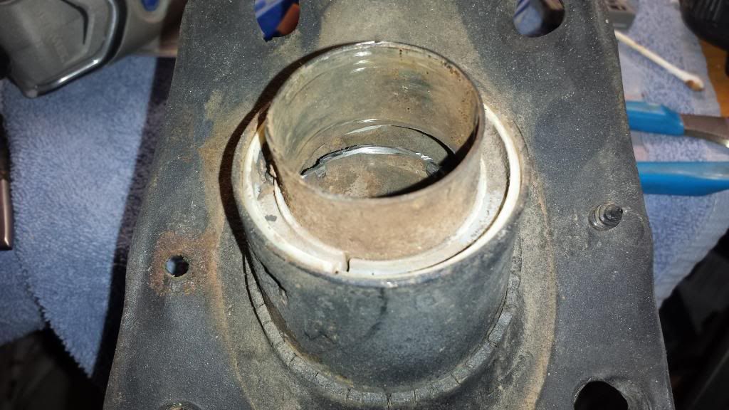
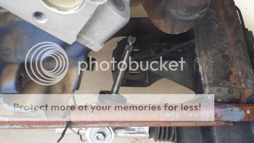
This is the engine compartment end of a factory 1968 Mustang/Cougar steering column, with the hollow rag joint shaft pulled out (it’s a friction fit to the steering column shaft on the inside). Basically the idea is to cut the inside column housing down low enough where we can press a bearing into the outer housing.

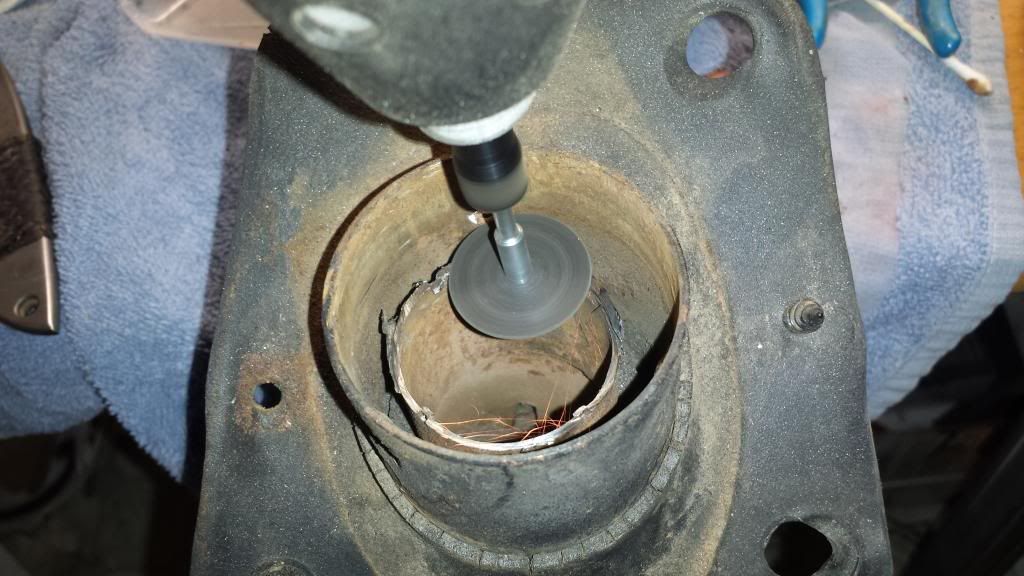
Here you can see me cutting it out with a dremel tool and a cutoff wheel. The entire cutting process took less than two minutes total.

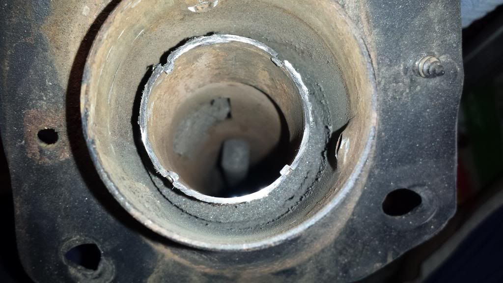
Here’s the inner housing cut out and removed. You can also see the male end of the steering shaft inside the column below. I used another of these shafts that I got from work to make my u-joint adapter, but you could easily use any piece of 3/4" diameter steel and do the same thing…you’d just have to grind the 3/4" DD into it to mate with the u-joint.

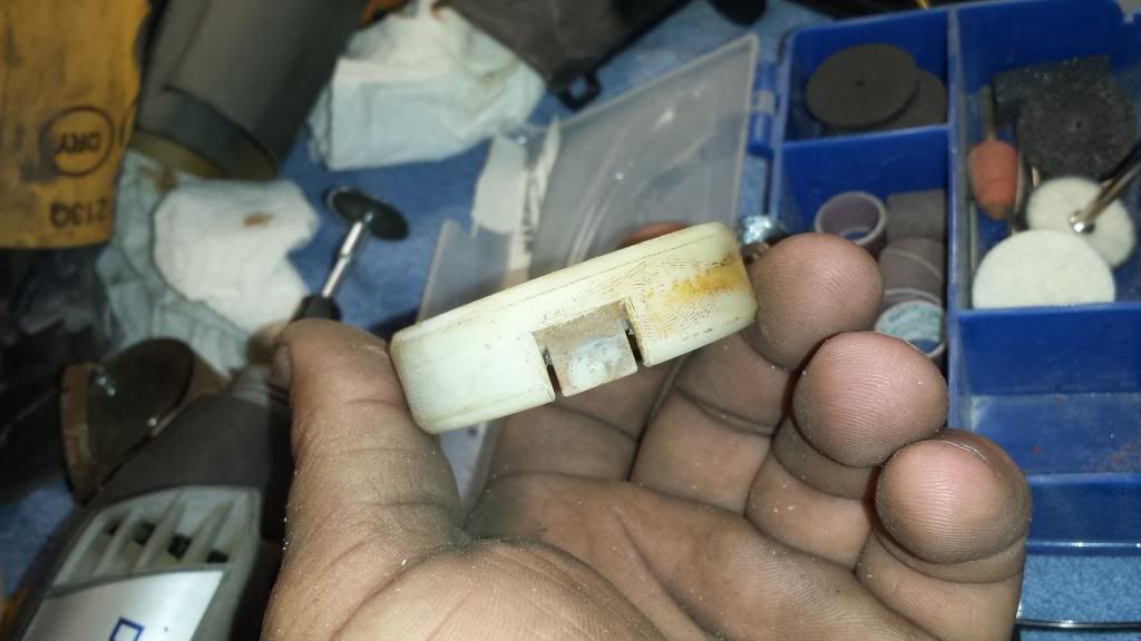
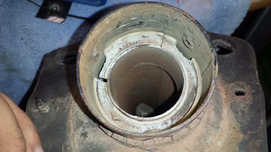
If you look at the first picture in this post, you can see this white spacer in the factory original column. Its purpose is to center the inner housing to the outer housing. Due to the way the column is built, we will still need a spacer for this purpose. I would have preferred to use 1/4" keyway stock for this (three small pieces pressed in would center the inner housing), but I didn’t have any on hand and reusing this spacer wasn’t too difficult (though I did crack it lol). Basically you just have to extend the indentations the factory put there to clear the set screw bosses as I illustrated in the pictures. After that, tap it (more gently than I did!) back in, and you’re all done.

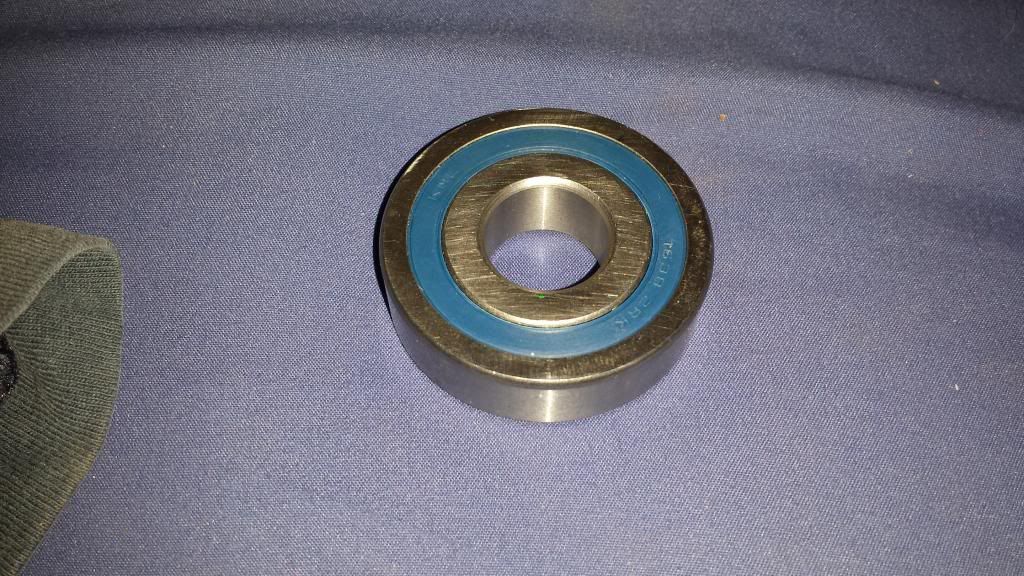
Here is the bearing I ordered. It’s 2" OD, 3/4" ID, and 9/16" thick. I used the thickness to determine how deeply I cut the factory inner column housing. Basically you want the centerline of the bearing to end up just a bit deeper than the centerline of the set screws. The outer housing is 2.10" ID, but those set screw bosses are a bit under the 2" that we need to fit our bearing. More on how to deal with that in a bit though.

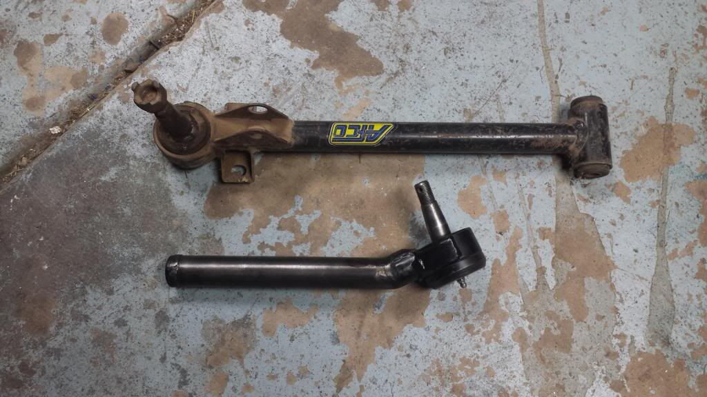
These are both of the pieces that make up a factory steering column shaft. The threaded end of the solid shaft (this one is extra…there is still one in my column) bolts your steering wheel on, while the 3/4" DD end slides a few inches into the end opposite the rag joint on the hollow tube. This is what provides the ability for the steering shaft to collapse instead of spear you in the chest in the event of a head on collision. The way I adapted mine, this functionality is retained. Basically you need to cut down the hollow tube (after you cut it you can pitch the rag joint end if you like), then cut down the 3/4’ DD end of the shaft as well. As I’ve mentioned above, if you don’t have a shaft, you can use any piece of 3/4" OD steel…you’ll just have to grind in your 3/4" DD flats to mate with your u-joint.

Here are the pieces cut. You can see I cut off the rag joint end, and I also cut the threaded part for the steering wheel off of the solid shaft. The measurements here are semi important, as there’s a few key things you have to do to make it fit. I’ll explain more as we go through the rest of the pictures.

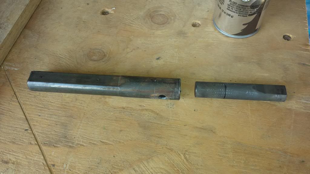
Here’s the two pieces you need to use. If you look at the solid piece, you’ll see a black line drawn on it. That is how far it needs inserted into the hollow tube so that the 3/4" DD end terminates a proper distance out of the column. The hollow tube needed cut a certain length in order to slip onto the solid shaft in the column, yet still provide the collapsing functionality. In addition, once you weld it, the hollow shaft needs to be far enough into the column not to interfere with the bearing placement.

Here’s the pieces fit together. You can see I’ve also drilled out the hollow tube to allow for two rosette welds. A bit of extra weld surface area is never a bad thing.

All welded up.

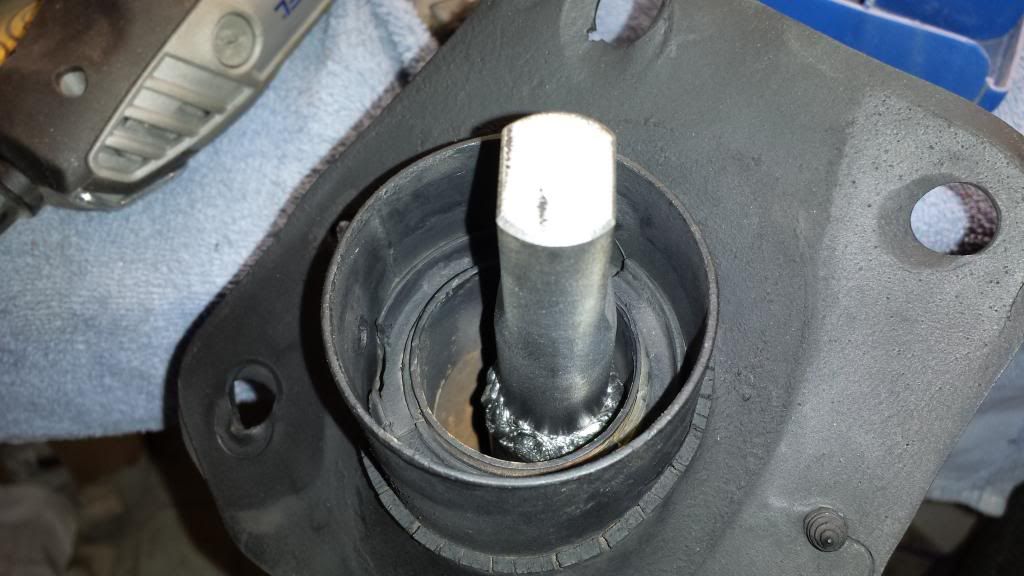
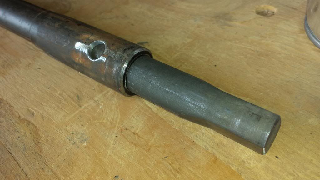
Here you can see the column shaft more clearly. Also pictured is the newly made adapter inserted into the housing (and over the column shaft a couple inches). As you can see the weld is below the level where the bearing will sit. This is a pretty simple, yet critical thing to overlook (I almost did myself) lol.

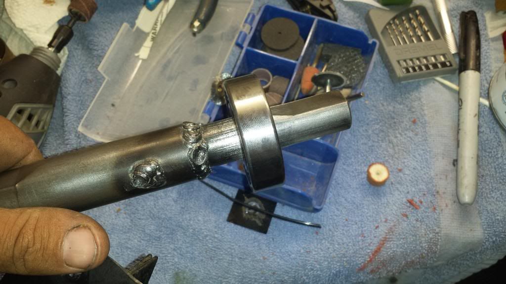
This is the bearing pressed on the shaft to the correct depth.

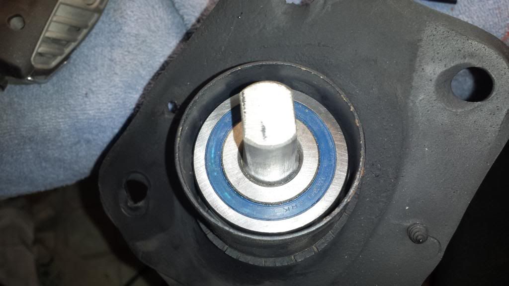
All done. You cant see it, but in order to get things to fit properly without major pressure on the bearing shell, I used my dremel with a small sanding drum, and tuned the set screw bosses carefully until the bearing was a tight press fit. Basically, I used a small rubber mallet and a socket to tap on the bearing. If it didn’t start with a solid tap, I’d sand a bit…then try again. Once it started, I simply tapped it in the rest of the way, alternating between the bearing and the shaft to ensure the spacial relationship between the two remained as I’d designed it.

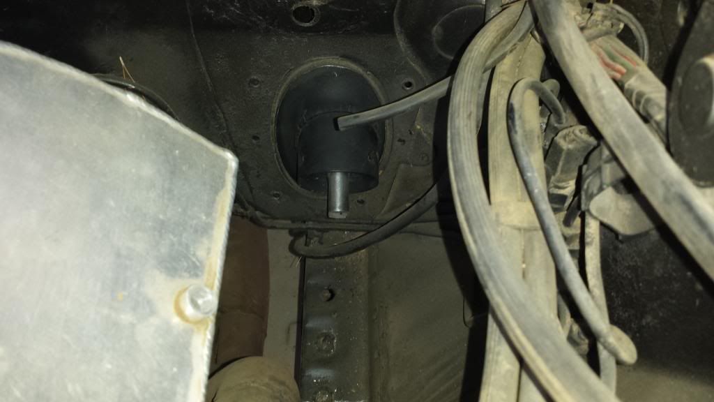
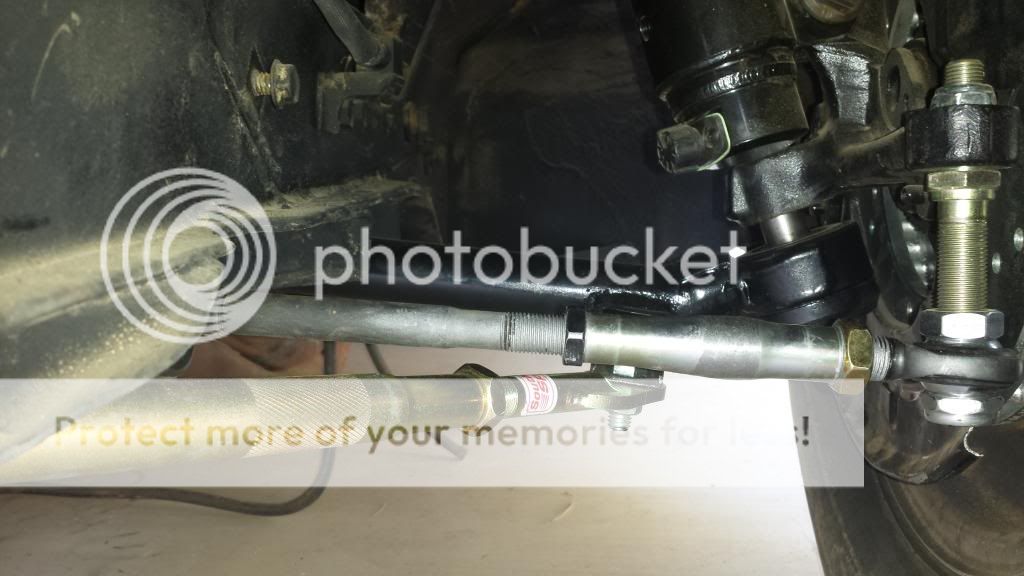
Here’s the setup bolted in the car. Nice and clean, with just enough extended to comfortably get a u-joint on without a struggle…without getting too close to the frame rail.

More to come as I get it done =p.

Got a little bit more done over the past few days. I got the rack mount bracket at least bolted into the car. I also got two of the three u-joints I ordered in as well. I’m now waiting for the slotted plates I ordered so I can finish off my rack mount bosses, and button the steering up for good.

Anyway, as usual here’s some pictures.

So there’s the setup bolted in…with the steering right about where I’m guessing it’s going to be. What I’ve decided to do is take a porta-power, place the ends on the front inside of each tire. I’ll extend it gently until the tires start to deflect a bit. At this point, the tie rods and the rack should make a direct line from where the outer tie rods are mounted, and through the body of the rack (much like pulling a string taut). I’ll triple check that the rack is in fact centered on the car (the tires will be on slip plates, and the porta-power will make turning them as a unit a breeze)…and that’s where the rack will be initially mounted with the bosses just tacked on. The rack mount bosses will be slotted vertically as I mentioned, so I’ll have 1.5" of adjustment on the vertical location of the rack. At this point, I can finally start checking the bumpsteer. I think the vertical adjustment will have the largest impact…but if in fact the rack needs to move forward or rearward, I’ll just cut the tack welds and grind down the mounting boss. I did buy four slotted plates just in case I totally bugger up the first pair of bosses I make, lol.

This is the splined rack connect joint. $35 wasn’t too bad a price for a stainless unit. Anyhow, as you can see…it’s awfully tight to the header tube. I believe it will still work, but man. I wish I could spline the rack input…because if I could, it would have been cut own already, lol. I’m going to try it as/is though, and if it doesn’t work, I’ll either roll the rack, or pull that input and see about getting it splined.

From here (once the steering is done) I’ll probably finish my driveshaft, set the pinion angle and weld my spring perches on…then mostly concentrate on the little things I can do to complete the interior. I did find a nice (not perfect, but nice enough) 67 Cougar driver’s fender in the back lot at work today…and since that’s the side that’s in the worst shape on my car, I’ll probably take it and mount it on the car. There’s also a passenger side door as well…if I end up needing one, lol.

Anyway, more pictures as the progress comes!