68 XR-7 Restomod Build

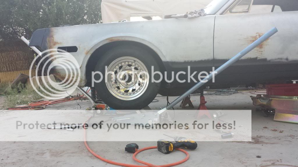
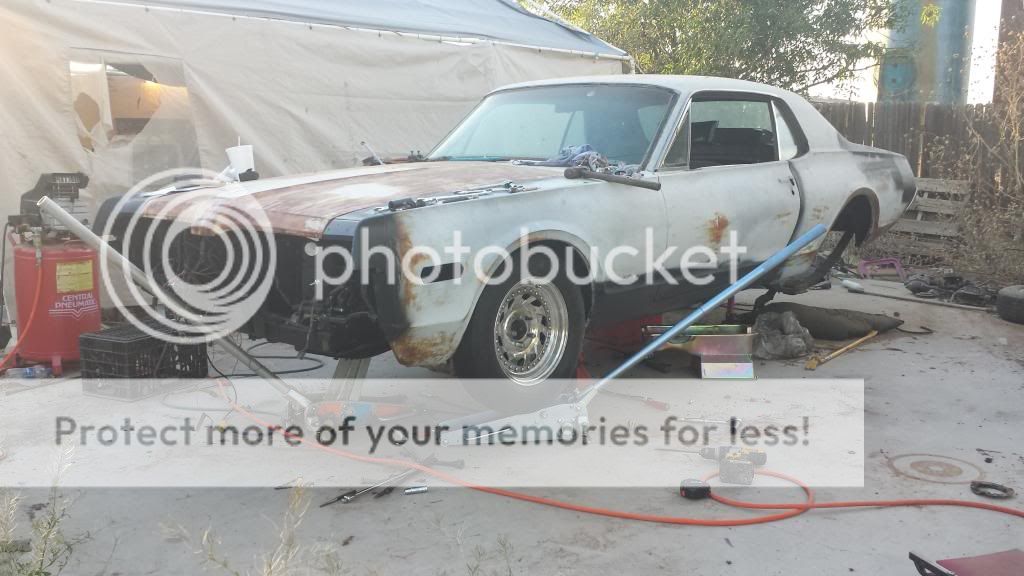
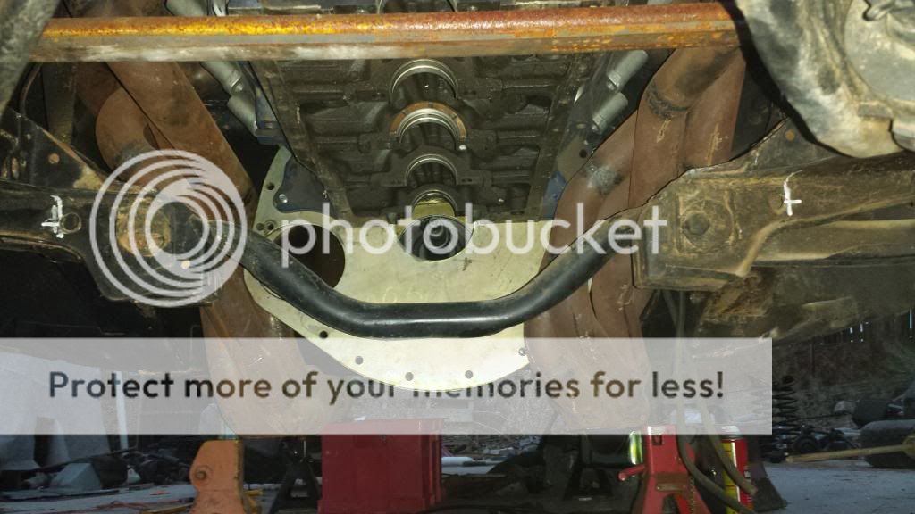
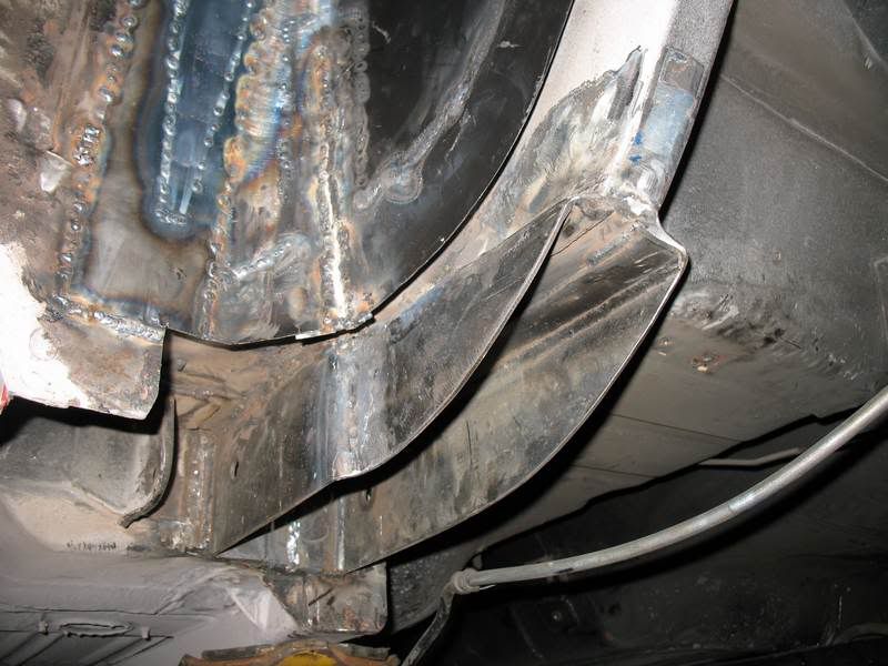
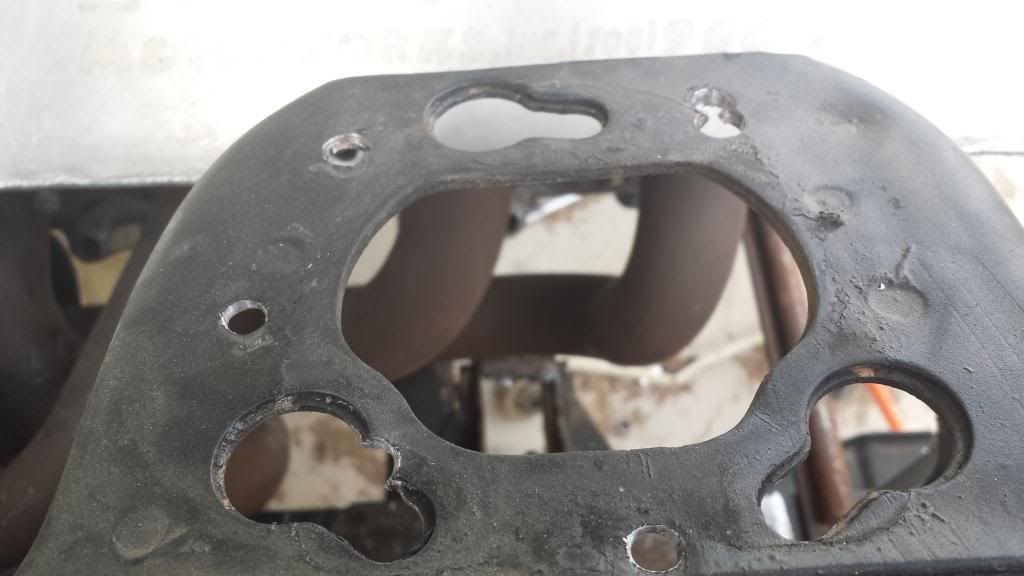
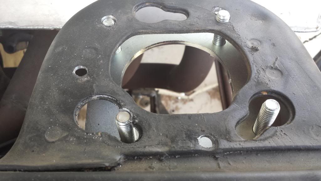
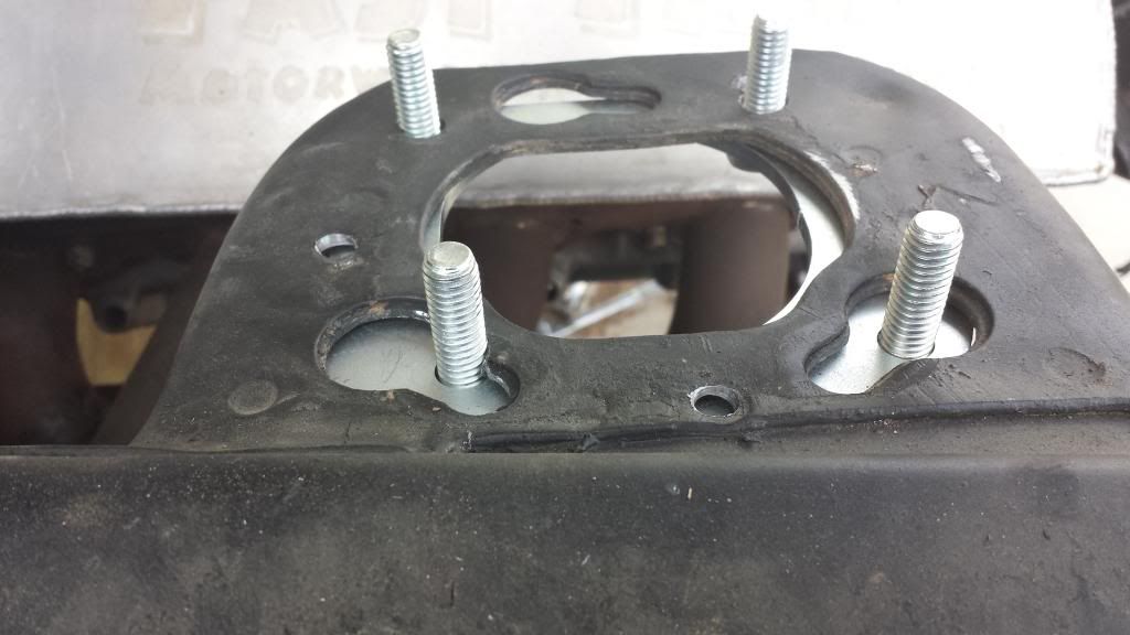
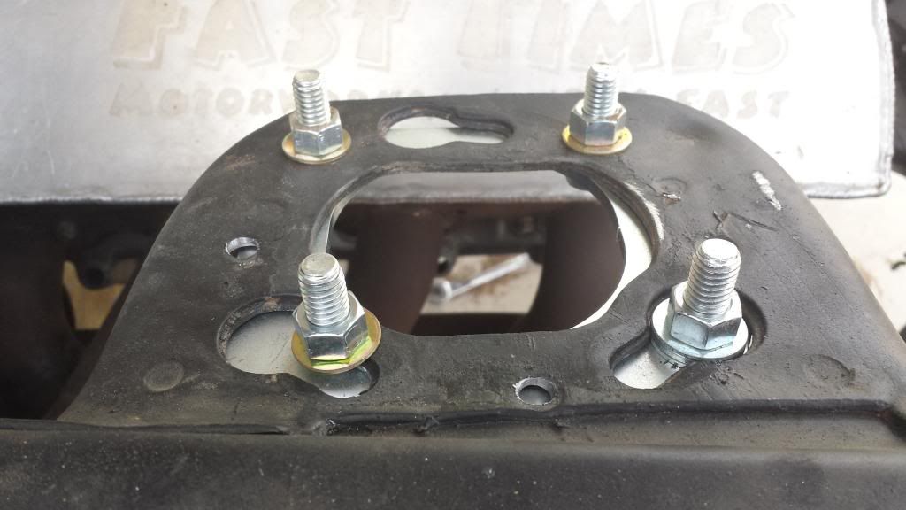
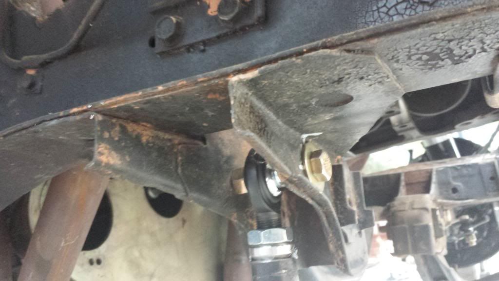
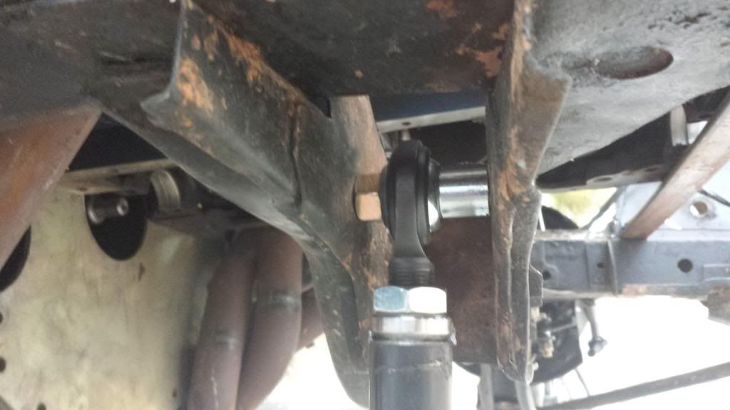
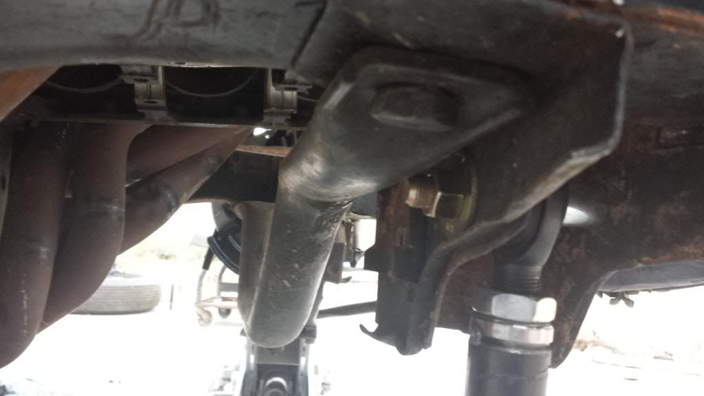
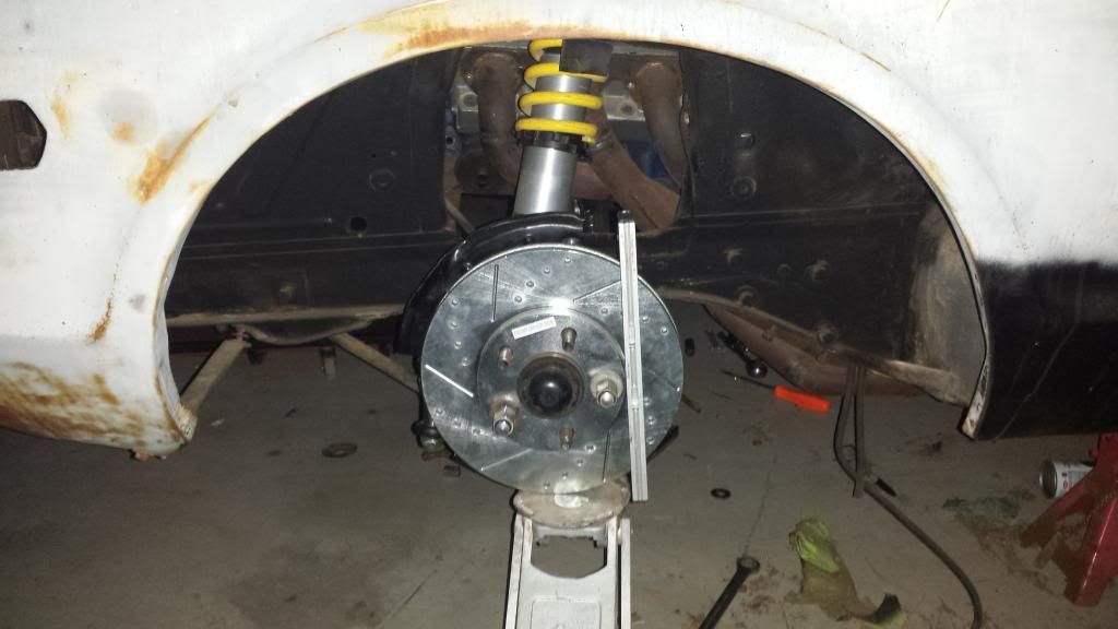
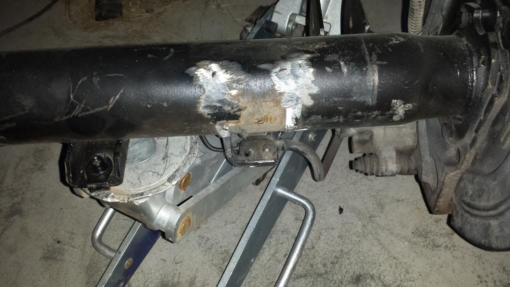
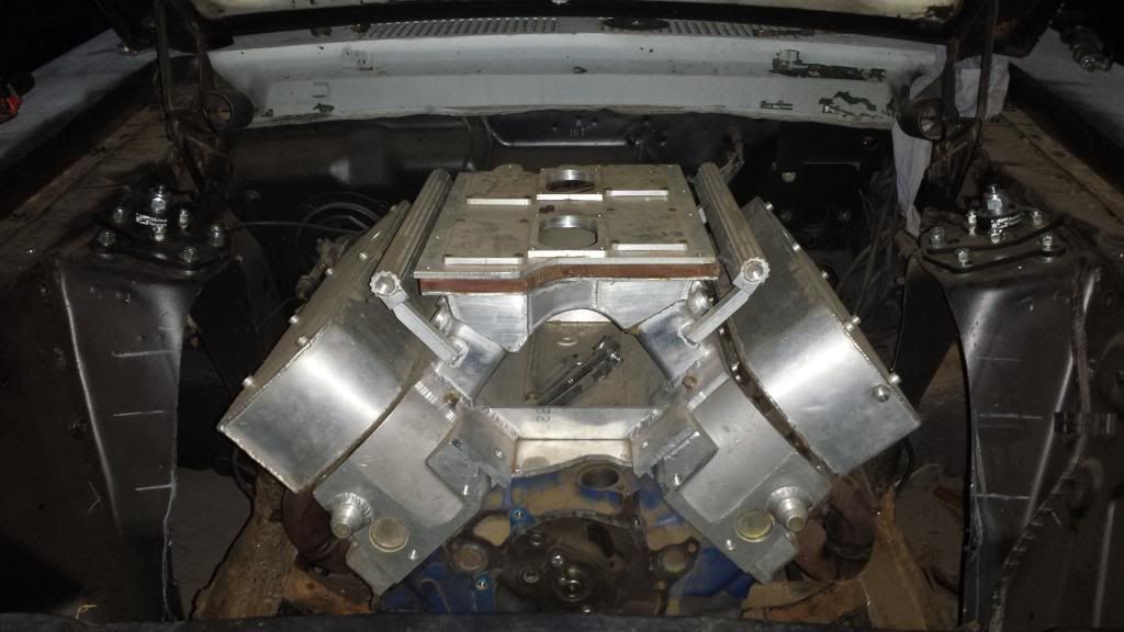
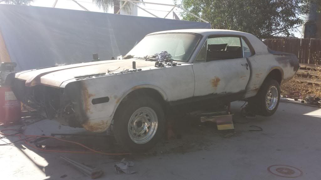
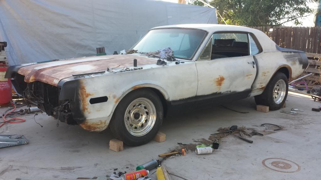
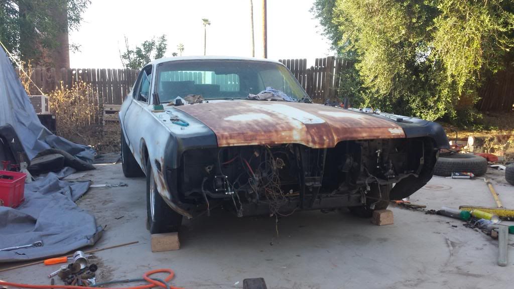
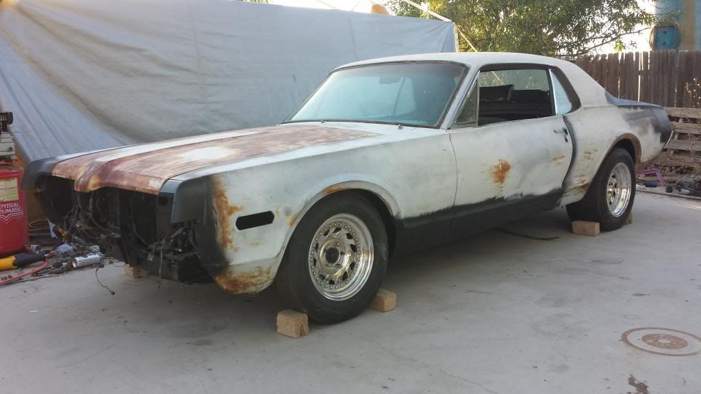
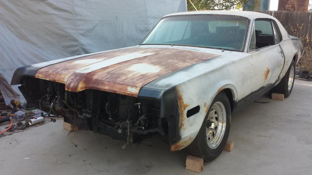
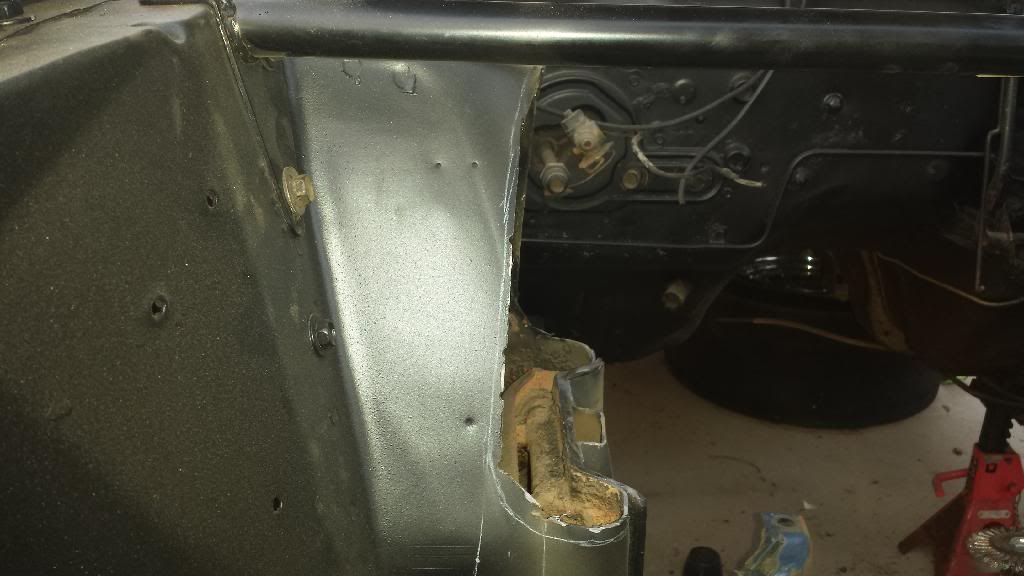
Sooo…is this considered ‘progress’?..or 'demolition? I decided it was best to just bite the bullet and get this done first, rather than spend three weeks dropping a dummy block (read: trashed 289 with no internals lol) with a transmission attached trying to get everything to fit with a minimal amount of swearing, blood, and all that other stress kinda stuff. Actually, I’ll show you a few pictures of why I decided I’m getting rid of as much of the shock towers as possible right from the get go:

This was my last 67 Mustang (during fitment…when I was done nothing touched)…same headers. The heads on this motor were high ports (.75" raised exhaust), and while the bolt pattern and port location (at least the height of the port) is the same on my current heads, I think they’re spread out just a bit wider. Thus…losing the shock towers. For your entertainment (if you’re bored), I’ll share a link to an old thread where I documented the fitment of the headers, in detail…lol. It wasn’t a lot of fun the first time around…for sure.

http://www.fordmuscleforums.com/makin-progress/482938-67-mustang-coupe-wip.html#post1473929

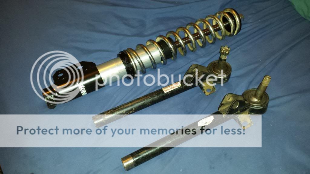
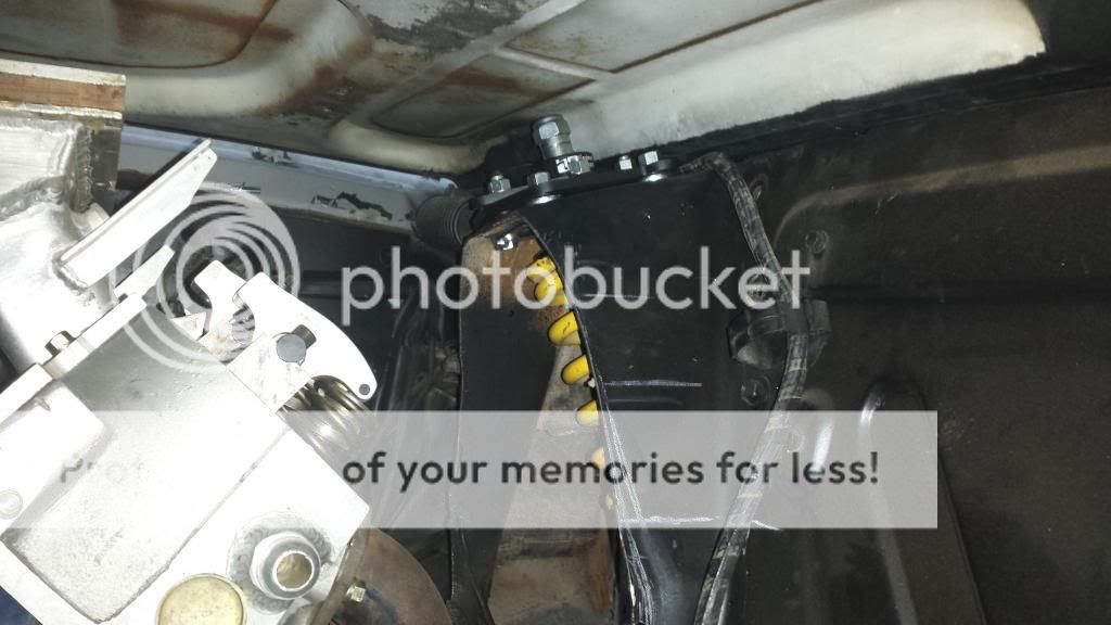
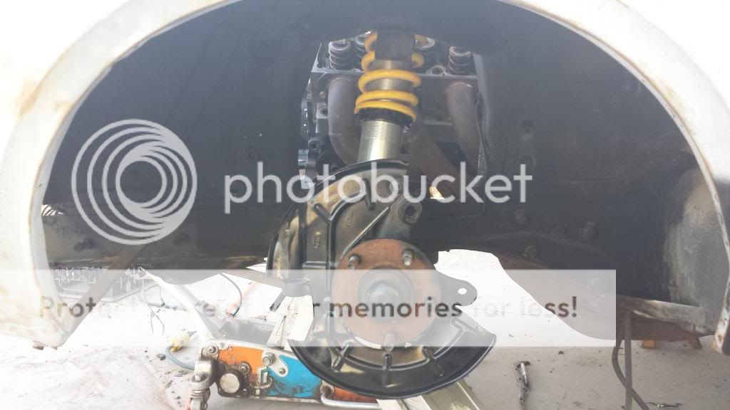
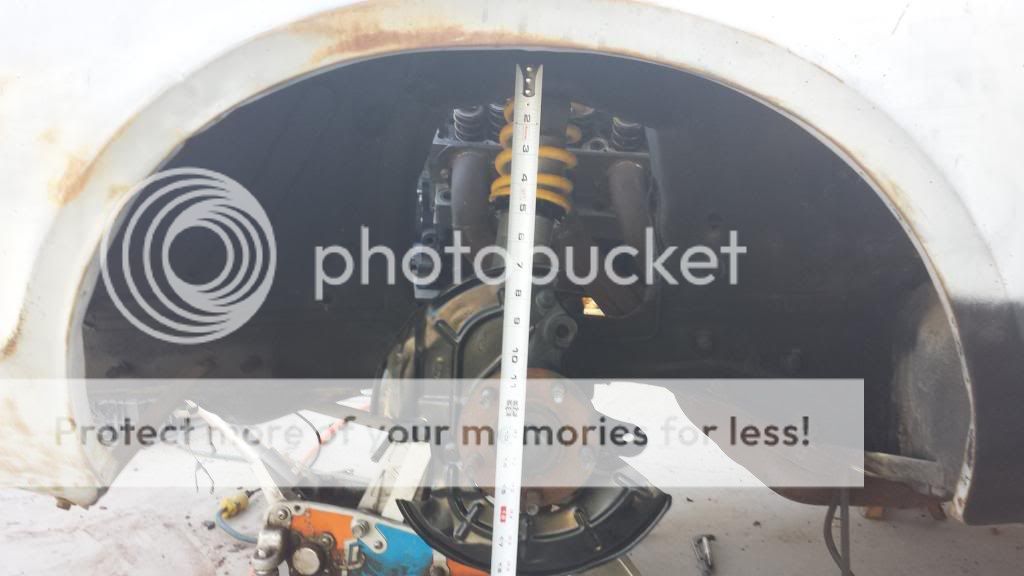
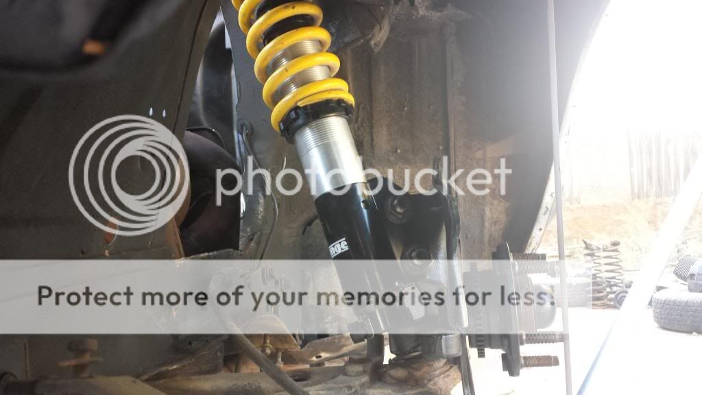
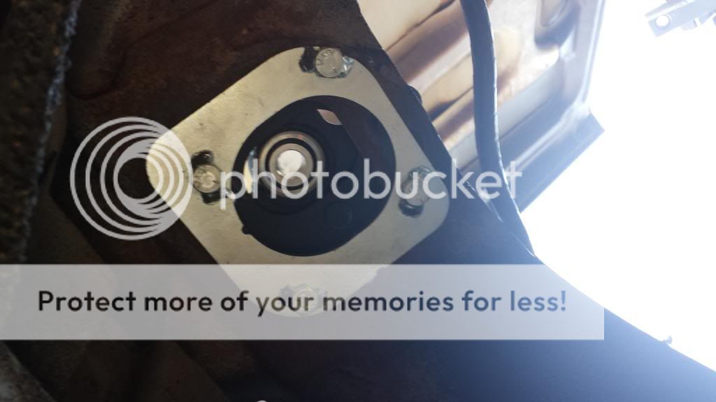
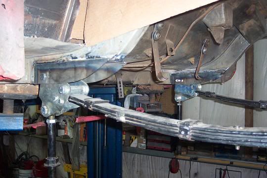
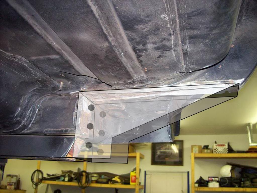
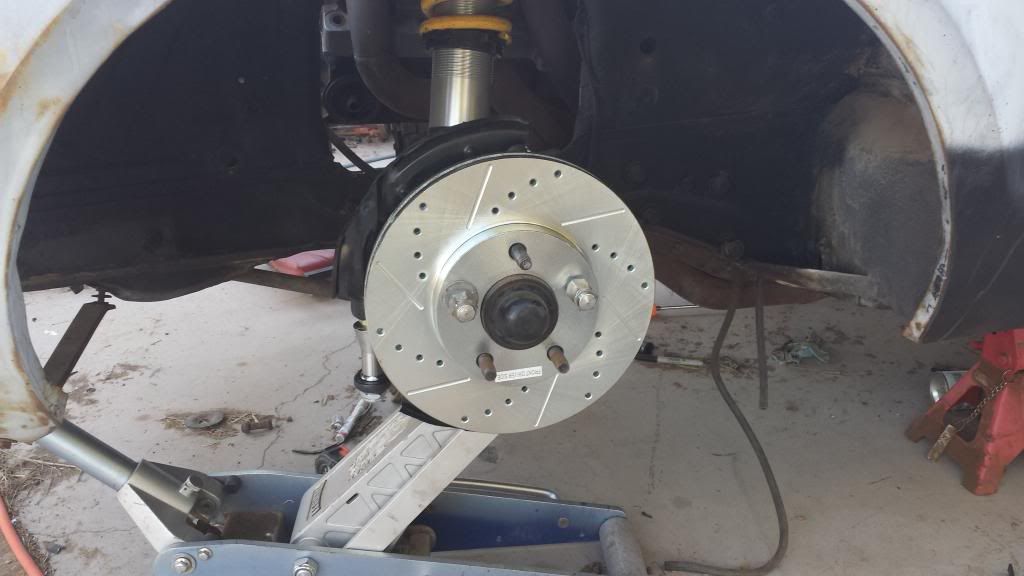
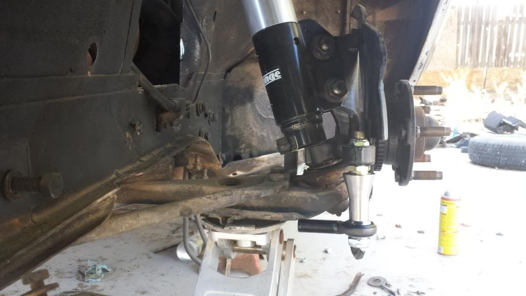
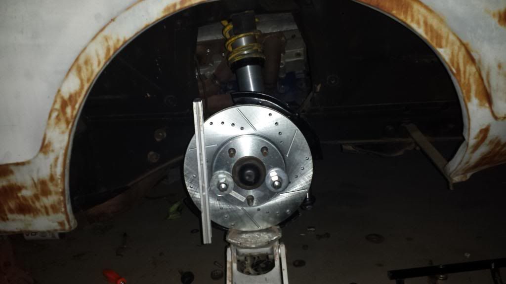
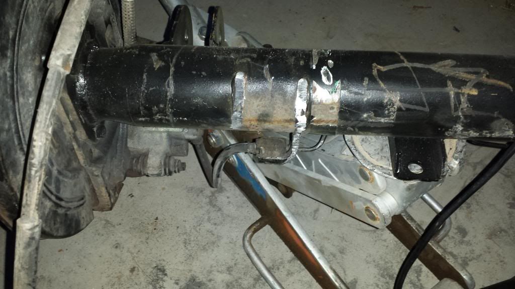
I’m probably going to change a few other things here as well, before welding it up. First…I may fab two brackets to run coilovers in place of the stock spring/shock/perch setup. Reason being…I have the right size threaded body coilovers sitting around from the dirt track cars…and I’ve got about 50 different sets of springs sitting around also lol. The only real benefits I expect to see from this kind of basic swap are maybe 20lbs off the front end (in a good spot!!), and more room to open up the shock towers. The top bracket will bolt under the existing upper shock bracket (which will be removed), and the bottom one will replace the spring perch. I’ll use simple stock car shock mount brackets welded to the appropriate sized plates to make the brackets. All of my shocks mount via rod ends at both the upper and lower positions.

Anyhow…that’s just something I’m kicking around…I’ve got a bit of time before I decide…but less shock tower (and thus more room!), is always a good thing.

On the cylinder head front…I should be ordering the reaming tool for my lifter bores here this week. I’m also going to be ordering my Megasquirt kit shortly as well. I’m going with the MS3x, and will be running full sequential spark and fuel (distributorless with LSx coil packs). The best part is that later, I’ll be able to run stacked injectors (2 injectors per port). The primaries will be sequential, smallish (perhaps 36’s or 42’s), mount very low, shoot basically horizontally into the port, and handle all the low load/rpm fuel supply. The secondaries will probably be 60’s, and will run off of batch fire. My biggest problem with the fuel injection setup I have at this point…is figuring out an air filtration solution which first…is capable of supplying 3000+cfm, and second…doesn’t cost $400 plus. I REALLY like the K&N sprint car air boxes (and they should be very easy to fit to this intake system), but they’re crazy expensive. I mean…$408 for JUST the freakin filter?? Seriously?! Here’s a picture:

So there’s that. Maybe I’ll try Racingjunk for a used one, lol. Any other ideas on that front would be very much appreciated.

Anyhow, there we have it. Moving along slowly but surely. I’m still hoping to have the thing running and driving by the end of summer (maybe, lol). Part of me thinks if I get it driving in the next 8mos…I’ll have really pulled something off though =p.

Well guys, a small update here.

I’ve decided to go with a strut type front suspension to eliminate the lower shock towers. With the lower shock towers, upper control arms, and factory steering/brakes gone, the weight savings up front will be pretty serious. With my goal for this car being what it is…every little bit will help.

Useful parts I’ll be eliminating/selling:
1968 factory power steering including pump and motor mount brackets.
1968 factory steering box.
1968 factory disc brake spindles, calipers, rotors (will also include the factory proportioning setup from the inner fender).

I’ll probably sell all of these parts locally on Craigslist…but I’d really appreciate if you guys could give me a rough value? I don’t want to over price them…but I also don’t want to just give them away either.

As for the part they’re being replaced with…I’m sort of designing my own system using modified fox body caster/camber plates, fox body coilover struts (strange 10 way), Mustang II/Pinto manual rack, and factory 1996-2004 SN95 spindles, rotors and calipers. I’ll be utilizing stock car type tubular single lower control arms with the SN95 sized screw in ball joints (mounted in the factory location), and a modified tubular strut rod (also mounted in the factory location). From all my research this should provide an excellent, extremely light front suspension for a street/strip type car with worlds better brakes and much improved steering. It also gives me the ability to change a few settings and put on wider wheels/tires for decent handling if I choose. Not to mention the fact that I now have an engine compartment that fits the massive top end I’m putting into it, lol.

Depending upon how complete the power steering set up is (and the condition) you should be in the $100-150 range. The steering box, control valve and cylinder are all worth about $25 each just as cores. Factory 68 disc brake setups have value. You should be able to get $100 for the pair of spindles and the prop valve.

Randy Goodling
CCOA #95

Thanks Randy, I got it all removed and up on Craigslist today.

It always amazes me how much crap is trapped up in the suspension and steering after so many years. Torque boxes too, lol.

Anyhow…I’ll get some more pictures up once I get the mid plate mounted, block removed…and get to work on the lower shock tower removal.

Hey guys, does anyone happen to know the measurement between the front wheel center and the fender lip on a stock 67/68 Cougar?

Thanks a ton!

FATMAN already offers a kit like this . we use here at heidts the fox body racks on our kits
http://www.fatmanfabrications.co/products/1967-1973-mercury-cougar-strut-ifs-conversion-kit/

The Fatman kit is $2100 per the link you sent…less struts, spindles, rotors, calipers, or steering. That puts it at $3000 or so, minimum, or $3700 if you buy it all from them. My setup has cost me less than $1300 complete with 2004 Mustang GT spindles, slotted/drilled rotors, and factory aluminum PBR calipers…Strange 10 way single adjustable coilovers with Qa1 springs, Maximum Motorsports 4 bolt 2004 caster/camber plates, Mustang II manual rack, and AFCO tubular lower control arms. The only fabrication necessary so far has been modification of the lower control arms, converting the lower strut rods to adjustable units, a bit of drilling (for the new shorter lower strut mounts and LCA mounts, and the caster camber plate install), and a new crossmember for the rack. Even if I bought new adjustable lower struts from one of the many vendors out there ($300), and had someone local fab me up a rack mount (perhaps another $300), I’d still be in at less than the base Fatman kit, with a complete setup and all new, very high quality parts.

Plus…and I’m fully aware that Heidt’s is a reputable company with quality parts…but I’ve heard so many horror stories regarding the quality of the Fatman kits its not even funny. As a professional installer I’m sure Heidt’s is capable of correcting any issues for their customers…but as the guy forking out $3000 for a kit to install myself, I don’t really feel that those issues should be possible to have in the first place, you know?

And for the record, in the weeks of research I’ve put in on this…I’ve heard of similar issues with AJE, Gateway, and even RRS.

I wasn’t going to post these up here until the install was finished, but here’s what I’ve done to it so far:

LCA’s and coilover setup. I’m using lower control arms from our dirt track car parts shelf, but new units are about $50 each…and can be bought pre-modified with the proper ball joint angle as part of the arm.

Caster/camber plates.

Ride height is about 13.5" from the center of the wheel hub to the fender lip…which from all I can find…is about an inch lower than stock. If any of you guys can get me the stock number from the center of the hub to the fender lip, I’d seriously appreciate it.

This picture’s a little deceptive because of the angle. There IS a bit of negative camber, but it’s nothing that the caster/camber plates and the adjustable LCA’s won’t be able to tune out. Track width seems to be just a hair wider than the original stock setup (I haven’t put the other side on yet to verify). Also, just for information’s sake, these springs are 10-450’s (10" free height, 450lb/in). The reason they’re in there is for a ‘stop’ of sorts, so I can verify geometry. My springs I’ll be using (14-175’s) should compress to approximately 10"…and so, these are a perfect interim spring. Basically I just jack up the LCA until the spring is tight, and I know I’m at the right suspension height for measuring.

With a wheel on the car.

All that’s really left as far as completing the initial work on this front end setup goes, is installing the shorter (roughly 12" long) lower control arms, fabbing up the adjustable lower strut assemblies and drilling for its new mount, and installing the rack. Once that’s all done, I’ll go ahead and lower the motor to where I want it, pull it out, fill in all the holes in the inner fenders, and it’ll be pretty much wrapped up.

It will interesting to see how you are able to reinforce the shock towers to carry all of the suspension force. This is a very original build, thanks for sharing.

Thanks for following, all of your helpful suggestions and information have been invaluable :slight_smile:. That goes for the forum in general as well. I’m really glad I found this place.

As for the bracing thing…I didn’t intend to go much beyond and export brace and possibly a monte carlo bar if I can get it to fit (if not, the front motor plate will have to do double duty). The caster/camber plates offer a far greater area on the load path versus the stock spring cups (I’ll post a picture below), which is awesome. The smaller tower, properly boxed in should be stronger as well. As long as I can get the force to the cowl area like it’s supposed to go as per the factory setup…I should be ok. The front end of the car should be a good bit lighter than stock also…partially from the aluminum top end, partially from a glass hood, and also the loss of the heavy steering, which should decrease the overall load on the towers as well.

All in all, just from mocking it all up…I’m pretty sure it’ll work perfectly. My main battle was with the steering. I’d originally intended to narrow the rack about 8" total in order to get it to properly work with the factory suspension pickups (bumpsteer is BAD!). This would move the steering input shaft of the rack inboard about 4"…which on a normal motor, with normal headers…would probably be fine. With the mess of 2" pipes I have to deal with though…any inboard relocation of the steering input points the 4" long shaft directly at header pipes. So instead I’ve decided to shorten the arms approximately 3" each, and move their mounting point outboard by the same distance. The only necessary modification is to drill new holes to accept the 3/4" grade 8 bolt the new arm will ride on. Returning the arms to factory length for whatever reason would simply be a matter of unbolting the shorter arm, and reinstalling the longer arm in the factory location. I’ll be doing the same with the locating strut rod…shortening it (as part of the process of making it adjustable) and moving the mount inboard, while leaving the stock mounting location there for a backup. The nice thing about this, is that it will also allow me to move the control arm locating point upwards by about 1", which will give me a nice chunk of negative camber gain before the end of the suspension travel…which should be right where the control arm goes horizontal.

I’d still love to get the measurement for the ride height from you guys, and if any of you have your front wheels off, a measurement from the upper control arm to the bump stop would be lovely as well. I’m curious just how much bump travel the stock setup has…and how it compares to what I’m putting in.

Anyhow, here’s a couple more pictures:

This is the underside of the caster/camber plates. That silver chunk of metal is 3/16" thick, and conforms to the 68 tower shape as though it were made for it. From this plate, four bolts pass through the top of the tower, and that’s what the 1/4" thick middle plate you saw above bolts to (and then the top plate bolts to that). All in all, its substantially stiffer than the factory spring cup, shock tower, and shock mount bracket, and spreads the load from the strut and coilover over a much wider overall area.

The white crosses are where I roughly eyed the new control arm mounts to be. I’ll measure properly before drilling of course. The shorter arm with a larger drop from mount to ball joint should allow the wheel to gain negative camber quickly in turns (my caster setting will be helping with this also…should be between 3° and 6° or so…we’ll see what I like when it’s drivable). The longer SN95 ball joints will also add some drop in the geometry at the spindle. I mean…while this is primarily a straight line car, it’s still a driver, and I want it to handle properly and predictably. A stable suspension geometry is a necessity in my eyes…regardless of the usage.

Besides, it’d be loads of fun to fab up some larger caliper brackets to toss on Cobra rotors, change my coilover springs and front/rear shock settings…throw some different wheels and tires on it…and actually be able to successfully drive it aggressively through a turn…lol.

67 Standard 289
Left 15-1/2"
Right 16-1/4"

67 XR7 289
Left 14-7/8"
Right 15-1/4"

Not sure why so much difference on the 67 Std.

Thanks!! Are those both 14" wheels?

Yes, 14" wheels on both cars.

Perfect!! That means my drop is approximately 1.5" give or take, well within the realm of reason :slight_smile:.

Little update!

I’ve decided to go ahead and relocate the leaf springs inboard. I bounced the ideas I had around with a friend over on FordMuscle (who’s used the Heidt’s kit on his early coupe), and came out with a workable plan that allows me to move it anywhere from 2.25" to 3" inward from its current location. This will give me a bit of tire clearance now, and all the tire clearance I need if I ever decide to mini tub. A couple of the side benefits are that I can make my forward mount adjustable (basically I’ll have one mounting point above stock, and one below), and that it will let me use the existing Exploder spring perches, lol. Basically I’m going to cut the rear frame rail out from the torque box back in a horizontal line, about 15" total. I’ll then take some .250" wall 4" square tubing, and cut the bottom out at an angle. Then you just drill a couple holes for the spring eye mounting points, clamp it up to the trimmed frame area…and weld the sucker in centered. I’ll make some offset shackles in the rear to line things up properly.

Here’s a couple pictures to show what I mean:

This is how my friend did his, using the Heidt’s kit. I’ll be doing mine a bit differently though, as shown below.

I edited one of his ‘in progress’ pictures to show how I’m going to do it (it’s NOT to scale!! I’m sure the low hanging part will sit a bit higher, the corners will be trimmed and contoured…etc). The Heidt’s kit is like 12ga plate…and I’ll be using .250" wall instead. Heavier…sure, but it ain’t ever, ever moving…and will make a stupidly solid mount for the subframe connector to tie to. Dennis has been hitting his with mid 10 second 408ci torque for a few years now without issue…so I’m confident mine is utter overkill, lol…which I like.

I also got my front lower control arms welded up partway tonight. I think I’m having some ground issues with my mig, as my welds aren’t laying down as cleanly as I’d like. I did manage to get enough penetration where I’m confident in the welds though…and after grinding them down, they’ll work. I seriously need to learn to tig though, lol.

If you’ll remember before, they were straight. I basically just cut a pie shaped wedge from the top down, then bent them to the angle I needed. The idea is to get a good straight shot for the ball joint to spindle at ride height. I’m thinking I should have angled it a bit more to allow some more droop, but we’ll see how it goes when I run it. I’ve got a coupe of sets of these arms laying around, so if these don’t work, fabbing up another set will be free.

So there we have it. I’ll spend tomorrow and the weekend finishing my LCA’s, cleaning and painting parts, and hopefully moving my leaf springs inboard. It’d be nice to be able to permanently bolt the rear end into the car. At that point I’ll be able to start focusing on the front only again…and maybe have it down on the ground so I can baseline the engine tilt.

You’ll probably notice the last update was kind of out of timeline for it being Saturday night lol. That’s because I typed it all up, but somehow didn’t ever hit submit :l. Turns out, I got my rotors and pads, strut rod brackets, and all of my rod ends from Speedway Friday (fastest shipping EVER). I’m still having some trouble with my welder…it’s intermittently shorting the arc, then catches up. The inconsistency made it really difficult to get a clean bead (my helmet kept cycling light and dark, lol), but I’m still positive I got good penetration and that it’ll hold.

Here’s a few pictures of what I got done:

First I welded the strut rod brackets to the LCA’s. They’re actually stock car lower coilover mounts (much like the ones I ground off the top of the LCA’s before). They work nicely for my purposes though. You can see better the angle that I fabbed into the LCA as well.

I’m not really one for bling lol, but they ARE a bit lighter than stock, came with good ceramic pads, and they actually cost me less than stock replacement rotors and pads would have at any local parts stores.

This is the drop steering adapter from Speedway. It’s a VERY nice piece, and even without the extra aluminum piece I ordered, it probably would have been fine. That support piece gives me a substantial comfort cushion though, which is nice. For those of you that didn’t know, it seems that a Mustang II/Pinto tie rod (that’s the application for these drop adapters) is the same shank size, taper, and length as a SN95. I thought that was interesting.

And this is the result of all the hard work. This is the LCA at full droop, with the LCA rod end mounted in what’s very nearly the position they will be when I’m done (remember those little holes next to my white locate marks in my previous pictures? My cross bolts for the LCA mount fit through them perfectly). Here you see the reason for the huge angle on the end of the LCA. Without it the ball joint would bind before the strut hit full extension. Too much of that (this thing should be wheels up every pass once it’s dialed in) and I’m positive it would snap.

All in all, I’m pretty confident that this setup will work well. All of my measurements have worked out as I hoped they would, which is a good sign lol. Tomorrow I hope to get my passenger side caught up to the driver’s side. At that point I’ll get some measurements for my swedged tubes…5/8" for the steering arms, and 1/2" for the strut rods. I may end up ordering some 5/8" rod ends with 1/2" swivels though, to replace the strut rods. I’m pretty sure the 1/2" swedged tube is strong enough (it’s actually 5/8" tube with 1/2" ends), but I kind of don’t like the look of the shank on the 1/2" rod end.

Anyhow, that’s that for today. It’s nice to finally see this front end starting to come together!

Cris, you’re a rocket scientist man! Very interesting work. I will be watching with interest…

Regards,

Robert

LOL!! Thanks man! I don’t know about a rocket scientist though. I’m more of a guy who has a couple good ideas on occasion, and is determined (or stubborn) enough to find ways to implement them. As I’ve said before…kind of like a blind squirrel who, despite the odds…has actually become semi adept at finding nuts =p.

Speaking of nuts, here’s today’s stockpile!

Suspension at ride height. My control arms are right at about 13.5" long, and I have a hair over 1" of upward travel at 4" from the mounting point before the frame. By the numbers, this should give me something more than 3" at the ball joint (in line with the strut…which has about 4" of travel left), and over 4.5" at the wheel. I’d like a hair more cushion, but I think this is sufficient.

This is the camber at ride height, with no adjustment. That half bubble on the level adds up to something under 1/4" per foot of slope, or about -1° (I think this number could be FAR worse with the constraint of keeping relatively close to the factory 67/68 track width). The caster/camber plate is maxxed out for positive camber, but I still have about 5/8" positive (inboard) adjustment on the rod end. Worst case…I’ll shorten the arms another 1/2", just to give myself a bit more inboard adjustment, as I’d like to have the caster/camber plates a bit more centered if possible.

Overhead shot of the strut rod setup. It looks WAY out in this picture, but if you raise the stock LCA, they actually line up almost perfectly.

A few pictures showing the clearance to the frame at ride height. I think this will work to be honest…but until I drive it, we really won’t know for sure.

So that’s it for now. I didn’t get to any of the rear end stuff, and didn’t get the other side setup either…but I still feel like I accomplished something. Tomorrow I’m going to hit the local surplus store for a couple of right and left hand 1/2" rod connectors and some all thread to replicate my strut rod so I can size it properly. I’ll also grab some 5/8" if its available, to simulate my outer tie rods as well. If things work out over this week, I’ll be able to get all the measurements for my swedged tubing, and get the rack mount position roughed in as well. After that’s all done I’ll move to the back and concentrate on getting the leafs moved inboard so I can put the rear end in.

Well, I’ve temporarily (I may actually never move them in, we’ll see) shelved the idea of moving the springs inboard. I need to get the car down on four wheels so I can move it over on the pad, and the easiest way is to cut the old perches off most of the way, and tack on new ones at the factory 43" width.

I also messed up on the design of my lower control arms, in that the strut rod setup I built doesn’t locate the ball joint in a fixed position horizontally. It locates it in a fore/aft capacity, but the ball joint is free to twist about 30° in either direction. As you can imagine, this would change the caster and toe at random. In addition, the position of the strut rod bracket places the strut rod on a plane with the steering. Luckily the solution to the first problem, also seems to provide a solution to the second problem. Basically I’m going to use an aftermarket attachment (similar to the stock strut rod attachment) to attach the control arm to the strut rod in a fixed position. I am also going to place the bracket that it bolts to, on the bottom of the control arm. This should allow me clearance on the steering arm, and correct the issue of the non-fixed position of the LCA.

Unfortunately I didn’t figure all of this out until I got both sides assembled and went to measure for my strut rods…along with mocking up the steering, lol.

Anyhow, here’s the pictures of what I’ve been up to, along with a better step by step of how I put the caster/camber plates in.

First the caster/camber plates:

You can see here I’ve already drilled out the mounting holes, as well as the spot welds holding the spring cup to the underside of the tower (the cup had been removed also). The layout of the mounting studs on the lower support piece of the caster/camber plate requires that one stud come up in the center of the original shock tower bracket hole, two in clean sheetmetal, and one just barely outside of one of the original slots. The one outside of the slot is obviously impossible to drill, so it needs to be routed out. I used a small round file chucked up in my cordless drill.

Here you see all the holes drilled out.

This part is important. You want it to JUST fit the studs. If its perfect, there is nothing to keep the bracket in place while you’re doing the rest of the work. If it’s too far from a clean fit (even if you can get the studs in there with a bit of force), it will spread the studs too wide when you draw them up through the holes, and the top plates won’t fit.

Here I’ve tapped the base plate up through the holes. A wooden 2lb hammer handle worked nicely.

I used the supplied nuts to draw it up tight…and you can see the washers I used to fill the hole on the near right. Perfect fit!..and part of why I placed it where I did. The drivers side is the same. In the second and third pictures you can see it all drawn up.

Mid plate installed.

All finished!!

This is how I chose to install my LCA. 3/4" spacer to the front, 3/4" rod end, and a nut behind it to hold it tight. I then followed up with a nut and washer on the outside. This pushes the LCA a bit rearward, allowing for a slight amount more forward triangulation.

Both sides installed at ride height (between 13 and 13.5" from center of hub to wheel lip).

Here’s a quick picture of the strut rod connectors I’ll be using to locate my lower control arms, as well as the swedged tubing I’ll use for both the strut rods, and steering adapters. The steering adapters were HARD to source! They need to be literally 4" long, with 5/8-18 LH thread on the outside, and 9/16-18 RH thread on the inside. I finally found some 7" long, and will cut and weld them to the proper length.

I also started grinding the perches off of the 8.8. As you can see I decided to leave some of it on there, since the spring perch doubles as a brake line bracket, lol.

Anyhow, that’s that for tonight. Tomorrow I’m going to finish getting the rear end ground down and the new perches tacked on. Once that’s finished, I’ll check wheel fitment again and see how it looks. I really think I’m going to need a wheel with 5.5" backspacing (my current wheels are 6.5"). I almost wish I hadn’t bought them, but they were worth much more than what I paid, so reselling them shouldn’t be too much an issue.

Oh, wait…one last thing…

Isn’t this thing a beast, lol??

Sooooo…I managed to get the rear end ground down to my satisfaction tonight, and set up in on the new perches for mock up. I centered it on the springs, and bolted it down with one u-bolt (I have to clearance another bracket to get the other u-bolt in) per side. I then went ahead and put my rear wheels on (with the 26" slicks), just to see what it would look like, and if there would be enough clearance to run the rather overkill backspace they have (6.5"). They did bolt up, and left me about 3/8" to spare at the springs. I am not, however…sure that they will end up clearing the inner wheel house. I think I’ll be needing wheels with somewhere between 5.5" and 6" of backspacing to actually run the car.

Here’s a bunch of pictures I took with the wheels on:

Both the front and rear suspension are obviously in full droop here. On the front, I’ve only got 4" of drop from ride height…but that should be sufficient for as much power as I’ll be pushing. I’ve got a feeling that once things are dialed in, I’ll be wanting to tame the front end lift anyhow.

I couldn’t help it…I wanted to see it on the GROUND, lol. Sooo, I chocked up the wheels (there’s no strut rods, remember!), and set it down. Not too bad! The front end settled right to 13.5" from wheel lip to center of hub…but the rear end didn’t settle at all. In these pictures there’s 17" from the same points. Now, there’s still no gas tank or interior to help lower things in the back…so I decided 100lbs plus would help drop it the way it needed to drop.

And that’s that. The rear end settled another 2" to 15" from wheel lip to hub. Also remember, these are 26" tires, and all of the ride quality/lowering stuff that comes factory on a Cougar is missing (about 3/4"-1’ worth…it wouldn’t fit with the Cal Tracs). I’m thinking a 28" tire, 1/2"-1" worth of lowering blocks to replicate the stock stuff, and a better offset rim will fill that gaping wheel well nicely!

My one problem of the day. There’s only about 3" of clearance from the bottom of the headers to the ground. I swear, these things have just been fighting me the entire way on this project! Either way though, it’s nothing a rosebud and a 2x4 for leverage won’t fix. Just sucks to have to do it.

Anyhow, there we have it. If I can get out there tomorrow, I may just spray bomb the thing satin black. This car will never see a professional painter, or likely even professional quality paint (though I may at some point tackle some of the bodywork myself) anyway…and I actually want it to look rough on the outside. The interior will make up for it when I’m finished, and the mechanicals should be drawing all of the intention anyhow.

Guess we’ll just see what tomorrow brings :slight_smile:.

You are cranking on that car,looks great!! :slight_smile: