68 XR-7 Restomod Build

I wonder why I haven’t received any notifications for all of these replies?!

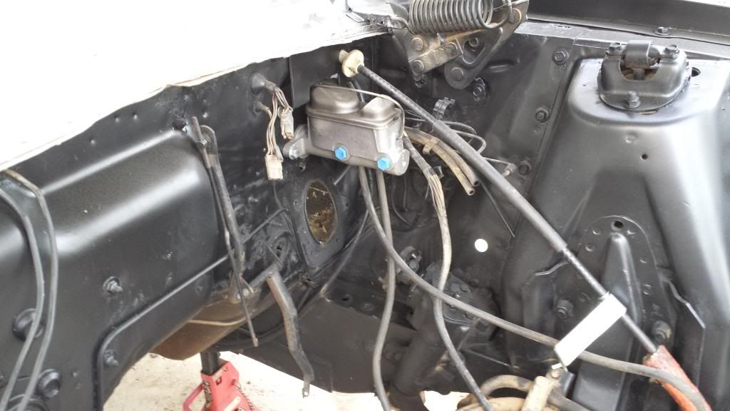
Things are coming along ok though. I decided that since this car is probably never going to see any kind of concourse restoration (too much effort to fix the rust, remove the cage, etc etc…all for a 2bbl 302 XR-7 lol), I wouldn’t go through the hassle of butt welding in the floor pan. What I DID do, is trim it to fit properly (meaning overlapping), coated all the overlap area with a weld through sealer I got from the guy who welds all of our large diameter cement lined water pipe together, then welded both the inside of the car, and the outside. I then drilled a boatload of holes (more detail on that below) through the new floor pan and the flange on the subframe, and rosette welded all of those back closed. After that, I smothered all the seams inside and out with Sikaflex 1a…then coated with a rust preventative paint. Here’s a few pictures:

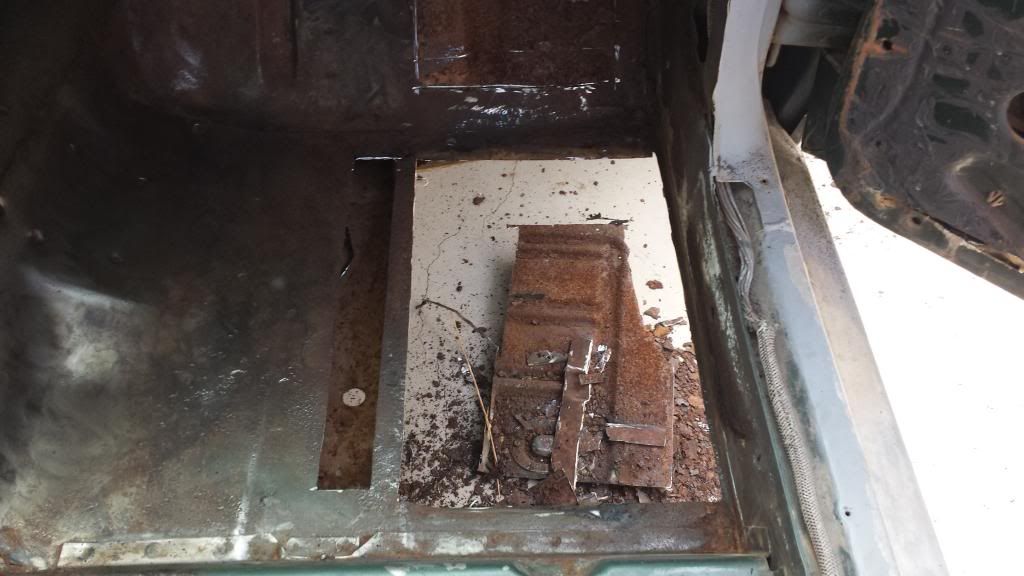
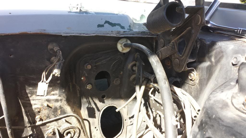
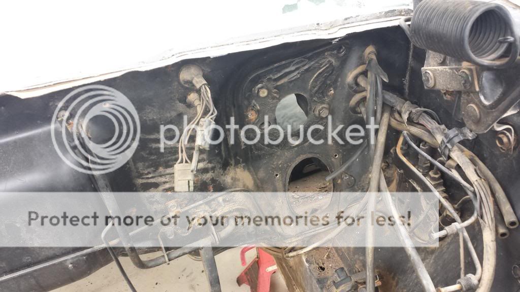
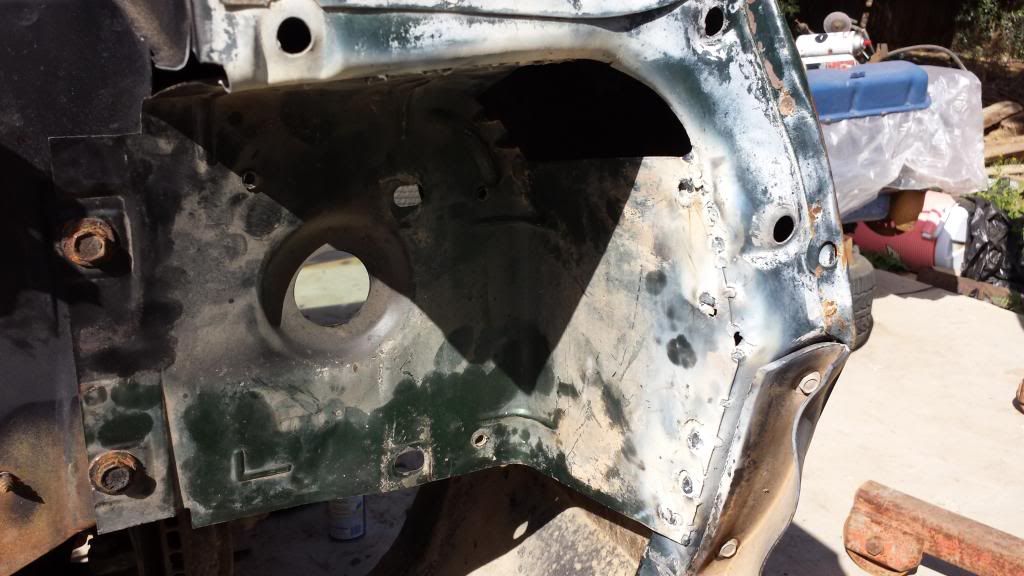
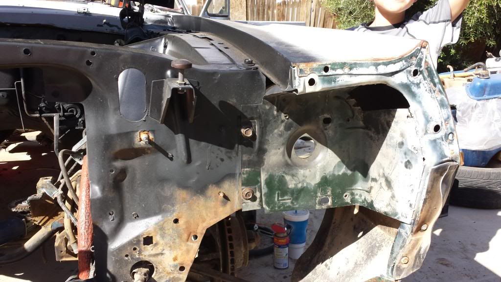
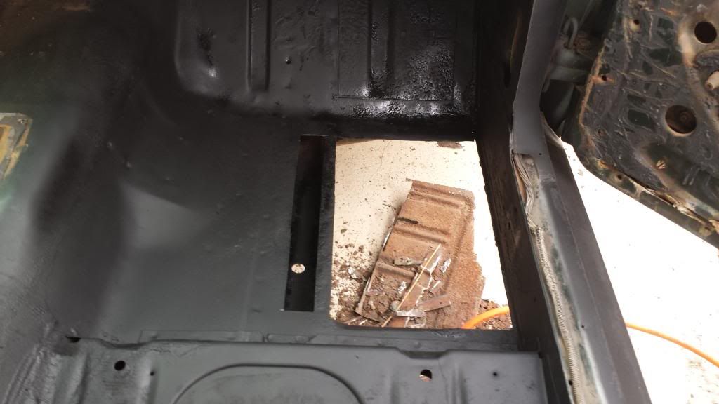
Cut out all the rust…

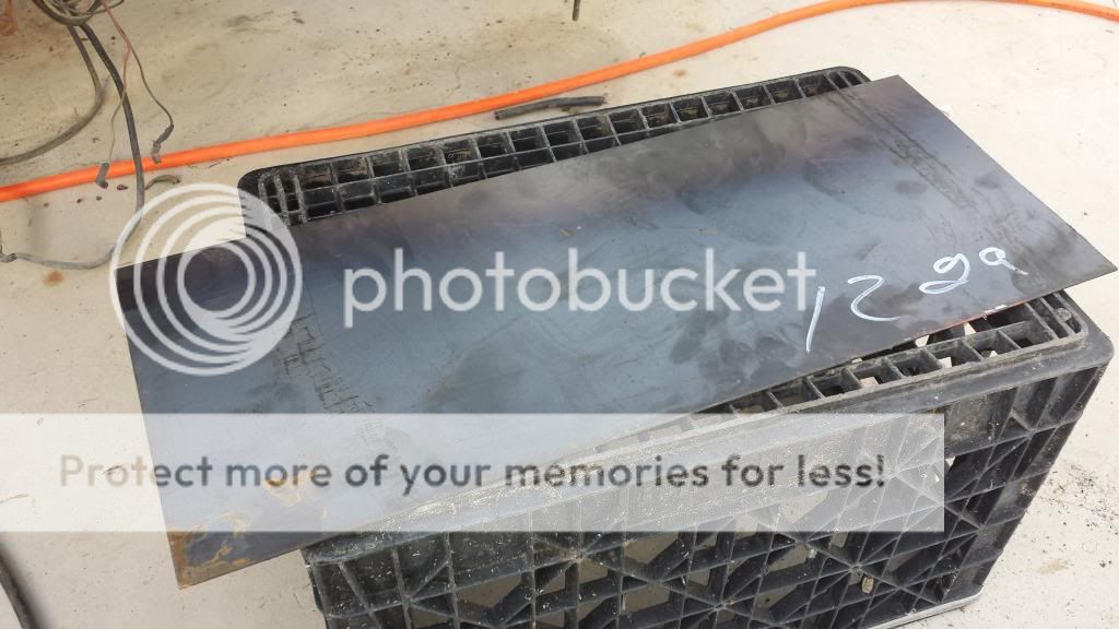
Test fit the (rather crappy) reproduction patch panel…it needed trimmed substantially to even come close to getting the stamping to line up. I finally cut the entire toe board section out, which helped tremendously.

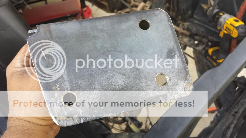
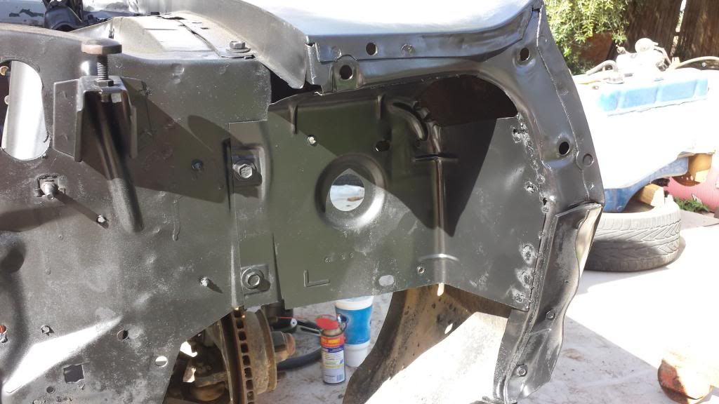
Next, I wire wheeled the crap out of EVERYTHING, then sprayed on the sealer…then coated that with the rust preventative paint…refit the panel, and welded it in. My method for welding it was kind of crude, but it was also incredibly effective. What I did, was screwed the entire panel in with self tapping screws…starting at the door first, and working my way over to the tunnel. I also screwed through to the frame flange as well. I then welded the perimeter (I hate welding sheetmetal…I learned this long ago welding a sump onto a fuel tank…), and one by one removed the screws and rosette welded those holes as well. The screws held everything dead tight, and didn’t allow anything to move or warp. I was pretty freakin generous with the screws, lol. I figured the more holes in it, the stronger it’d be.

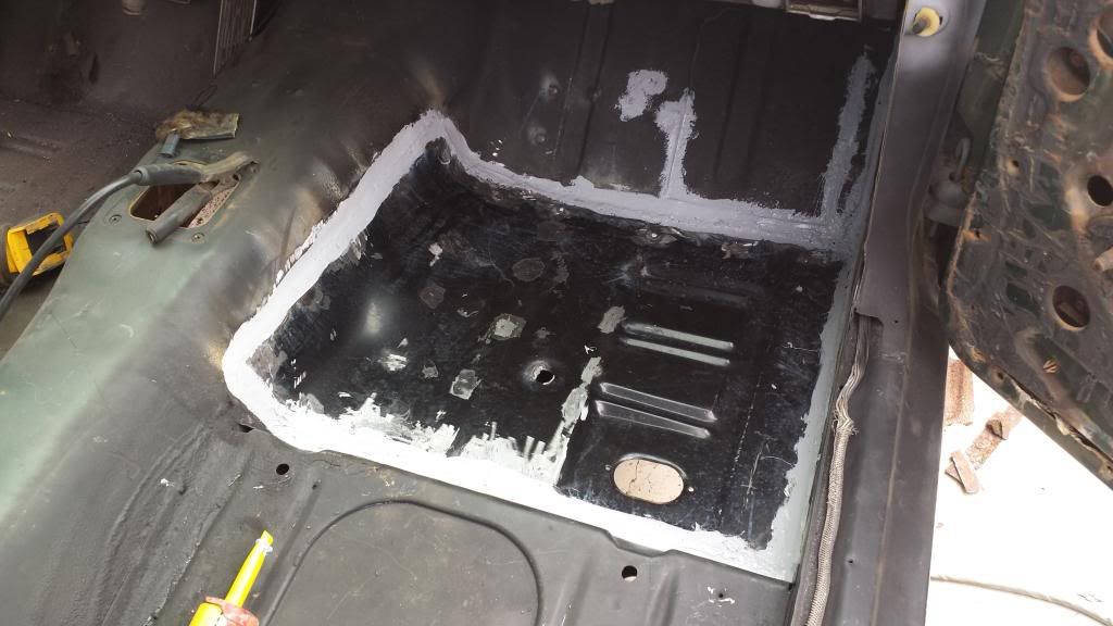
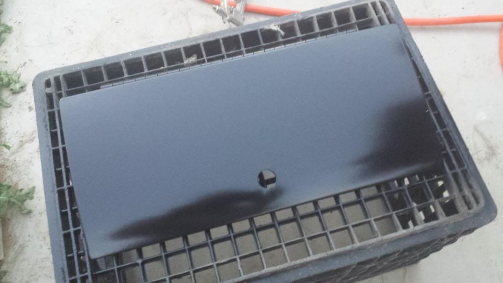
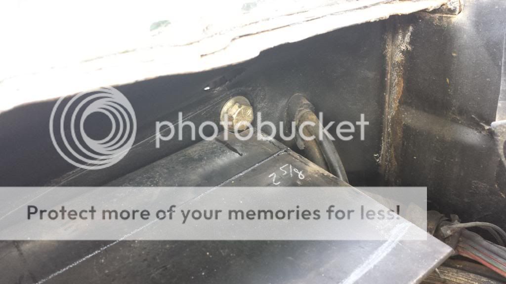
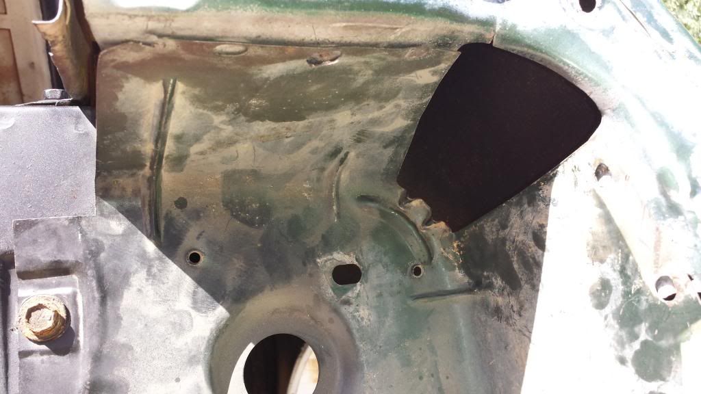
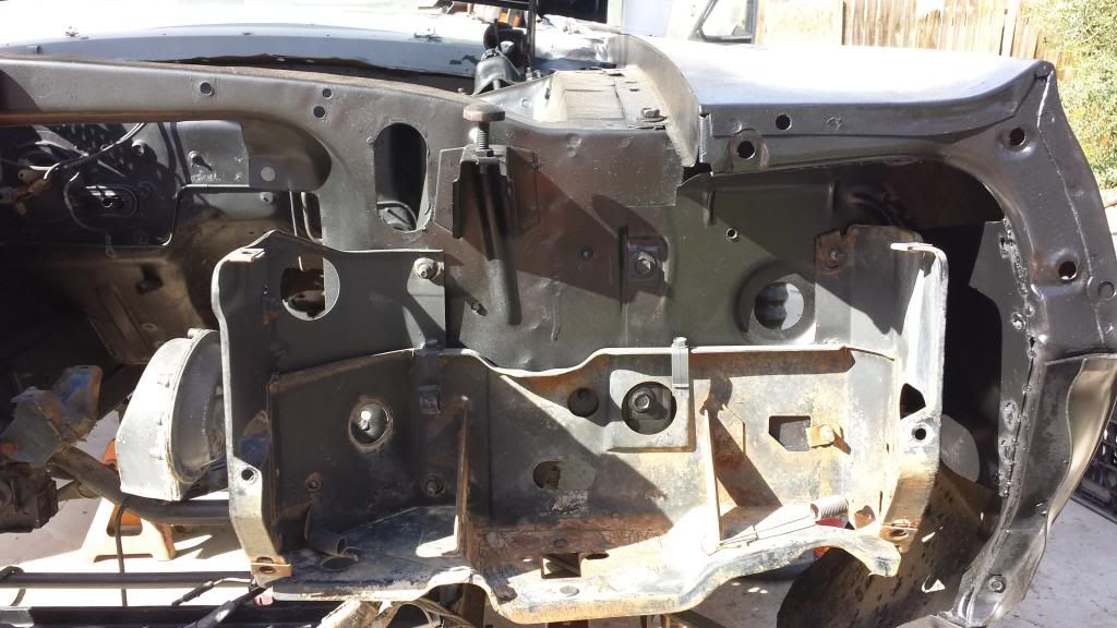
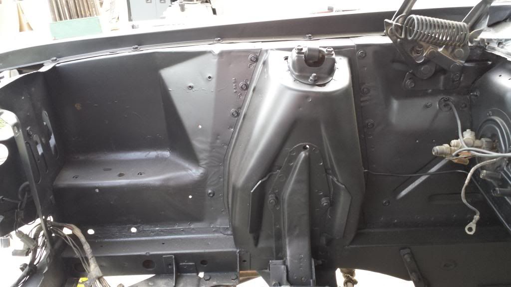
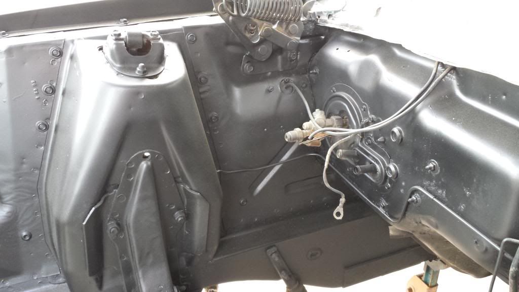
All sealed up. Sikaflex is great stuff, lol. It’s a polyurethane elastomeric sealant, stick to anything, will cure under water…and never fully hardens. Pretty cool.

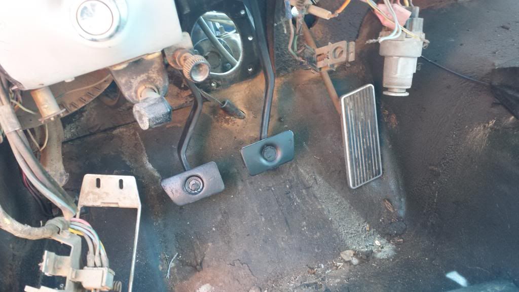
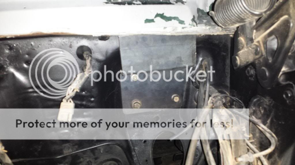
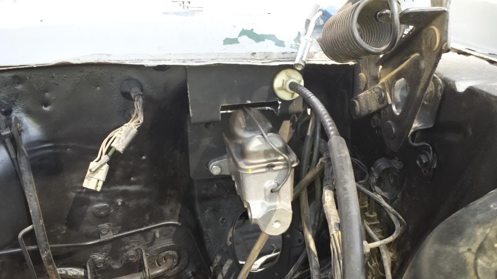
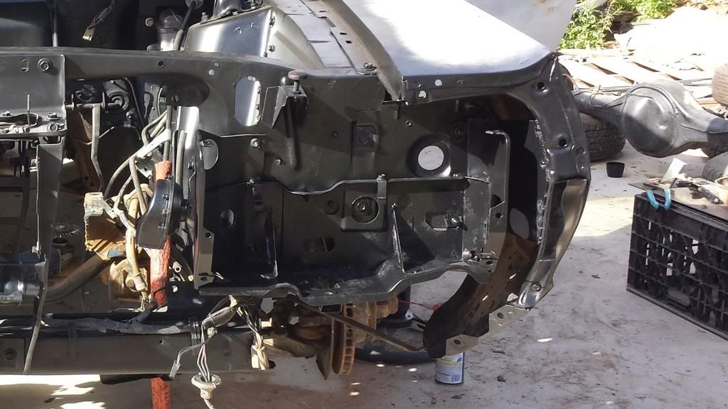
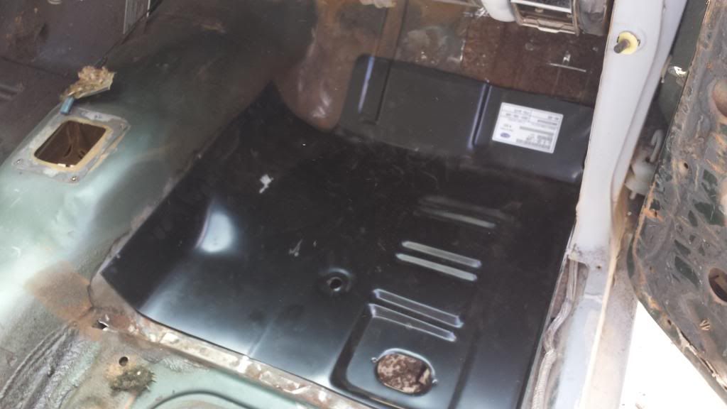
The finished job. Not the prettiest, but its solid as all hell, and will more than do the job I require of it. I’ll address the heater core and cowl vents to make sure they weren’t the cause (and fix them if they were) at a later date.

So now…on to my next issue. Wheel/tire fitment.

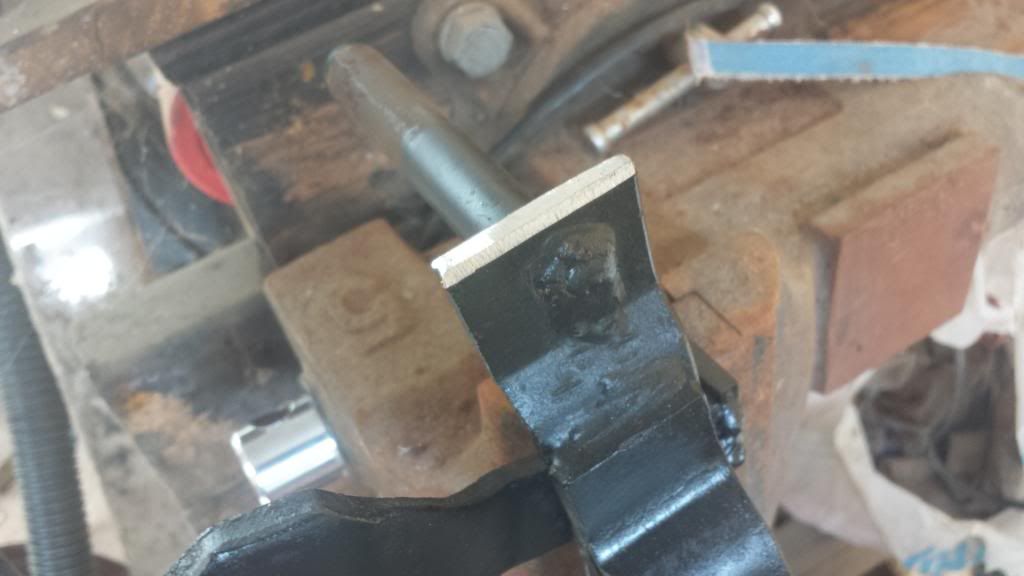
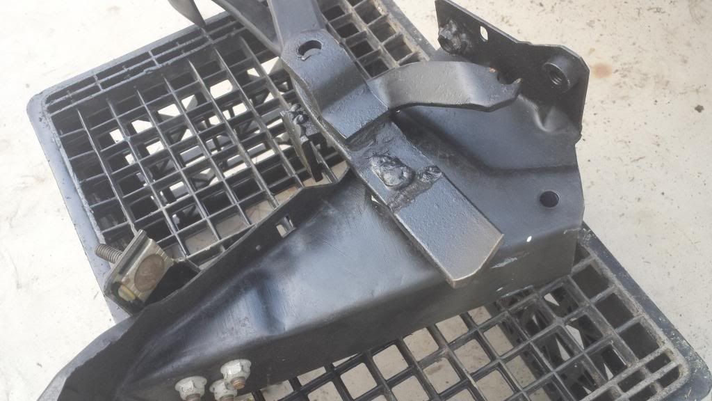
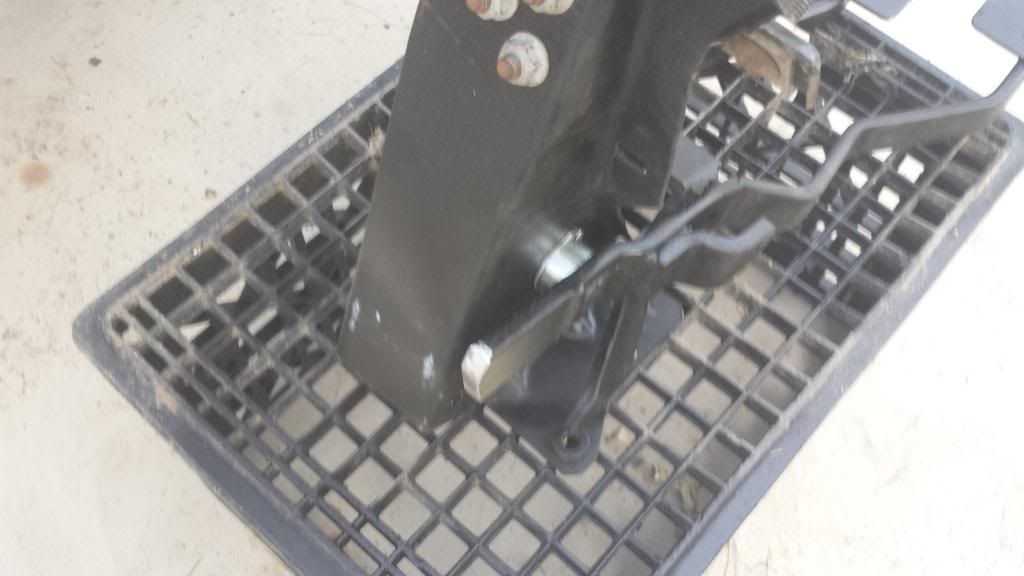
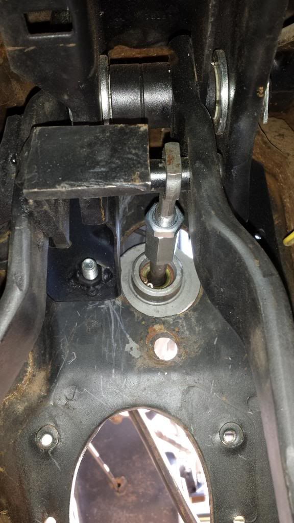
As I mentioned earlier…my wheels are 15x9 with 6.5" backspacing. The current tires are 26x10.5 slicks. This combination did NOT work. Even after cutting the excess metal off of the snubber bracket they wouldn’t fit.

Pesky leaf springs…

Anyhow, I ordered some relatively nice 1.25" wheel spacers, thinking this would be just the fix, and for the driver’s side (which was the side I test fit everything on), it absolutely was, the outer edge of the tire bulge was about even wit the inner body line of the wheel opening. A nice rolling of the inner lip and it would be perfect. The passenger side however, was now sticking out of the wheel well by a fair margin (even some of the contact patch). At this point I was thinking the rear end was installed incorrectly. Possibly that the Granada/Monarch/Versailles perches had a larger locating hole in them…and that whoever did the install just didn’t center it. Wrong. After loosening the u-bolts and being forced to pry the rear end from the pinion angle wedges…it was very apparent that the locating holes were precisely the right size. So I pulled the rear end, and started in on everything with a tape measurer. Turns out, the rear end is fine. Everything is properly centered from the wheel mount face to the spring perch. So, what’s the problem you ask?? Well…it appears that THE CAR is freaking offset on the rear subframe by almost an ENTIRE INCH. Seriously :l. The passenger side outer wheel opening is literally 7/8" closer to the leaf springs (which are mounted very solidly to the frame on both sides I might add) than the passenger side. This means I’m going to have to pick up a smaller wheel spacer for the passenger side, which is really just kind of silly. I mean…I don’t know if this is common with Cougars…but I’ve owned five separate 67 Mustangs, all utilizing 10" rear wheels…and never had this problem.

Have any of you had that kind of issue with these cars? How did you fix it?? Was it able to be fixed…? Kinda sucks!!

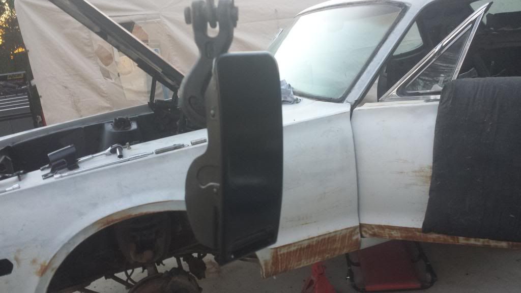
Anyhow lol, here’s a picture of how the current wheels and tires look on the driver’s side. Not bad…but a bit short in my opinion. Good thing I’m probably going to be switching to a 28" tire anyhow, which will help fill the wheel well some.

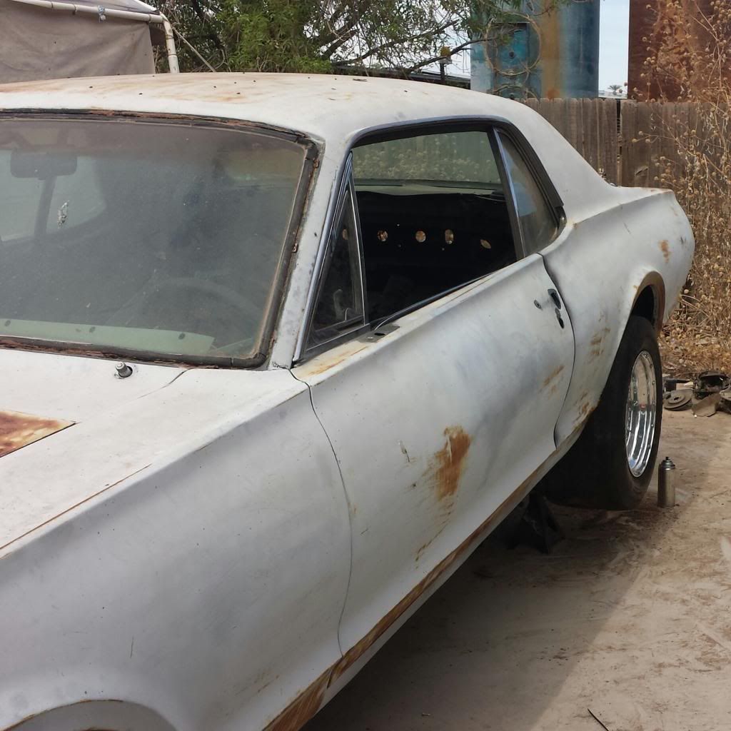
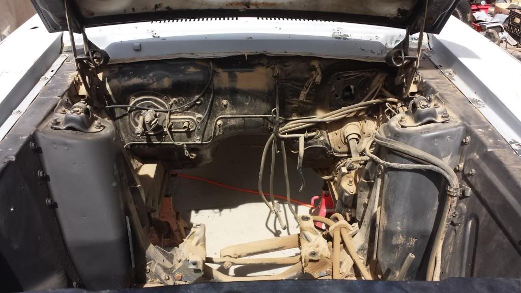
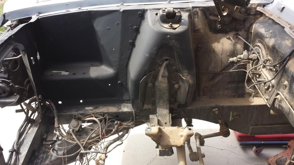
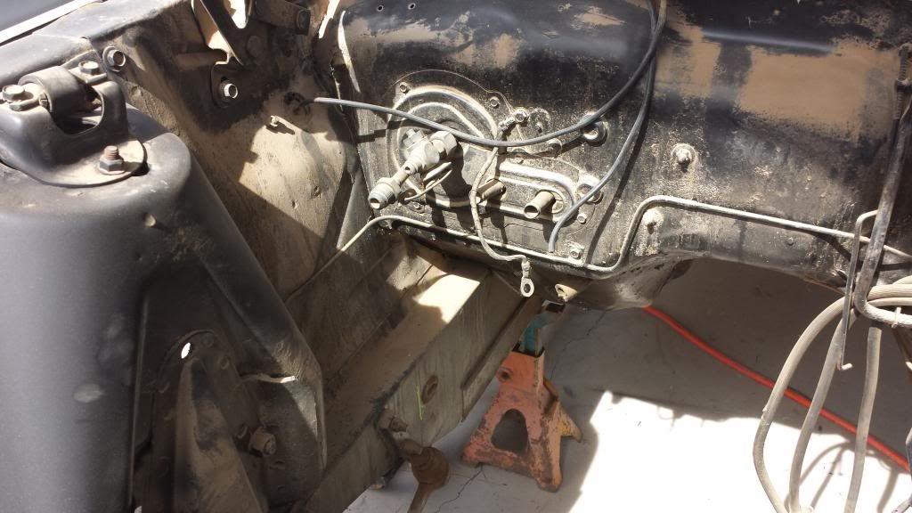
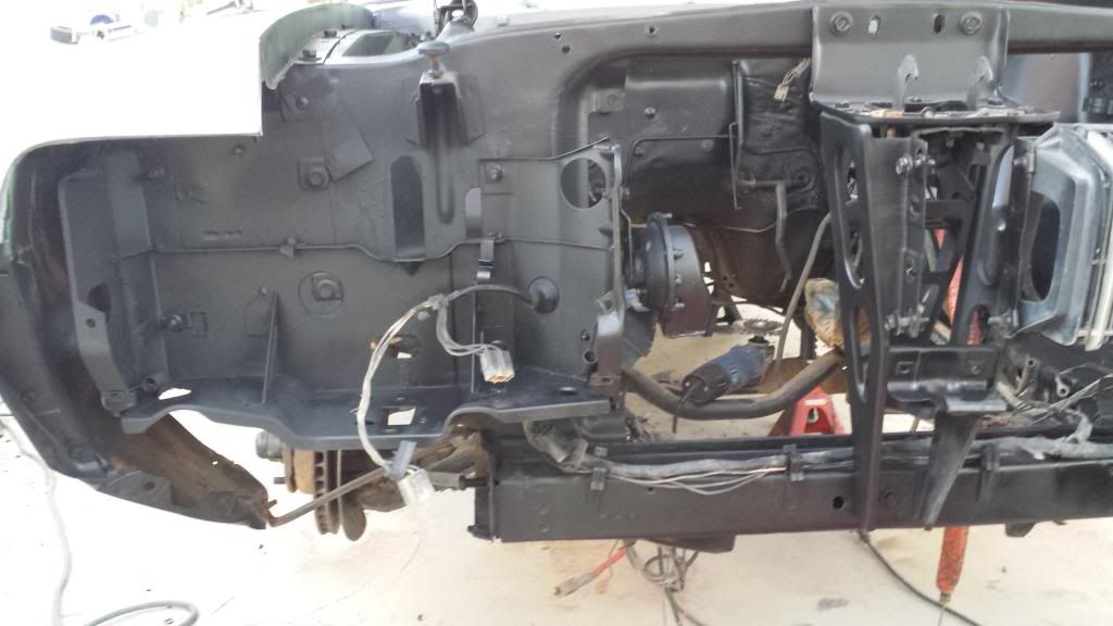
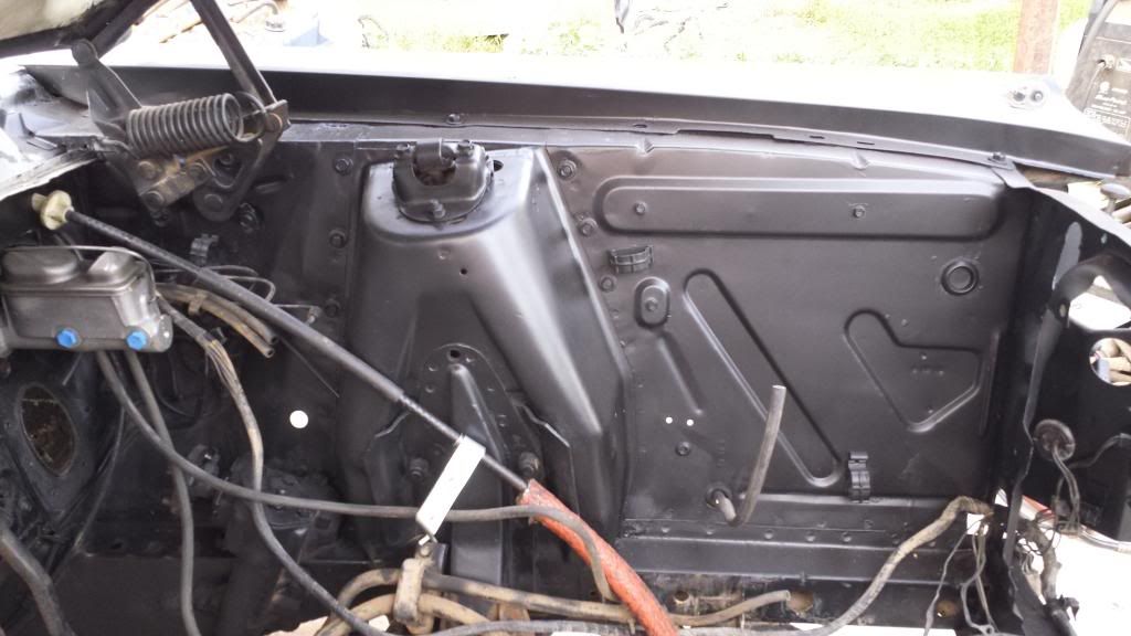
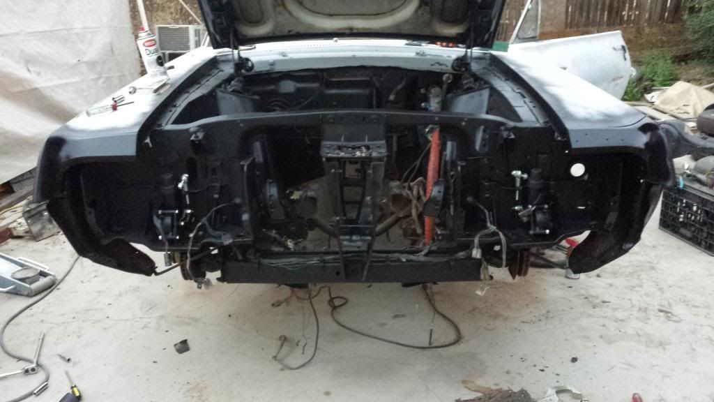
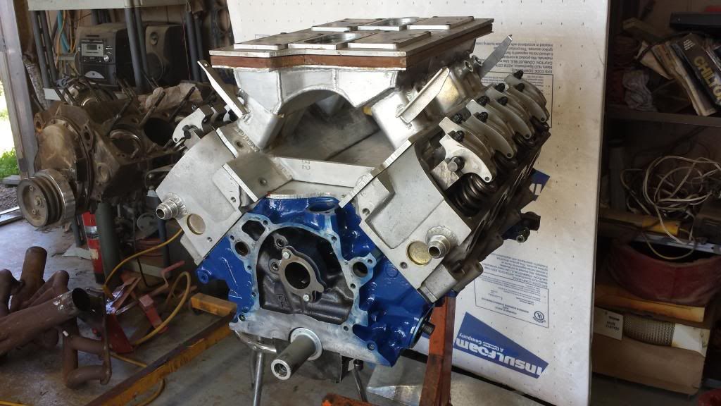
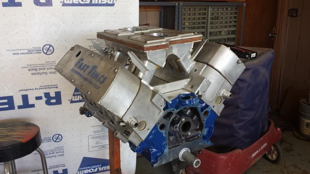
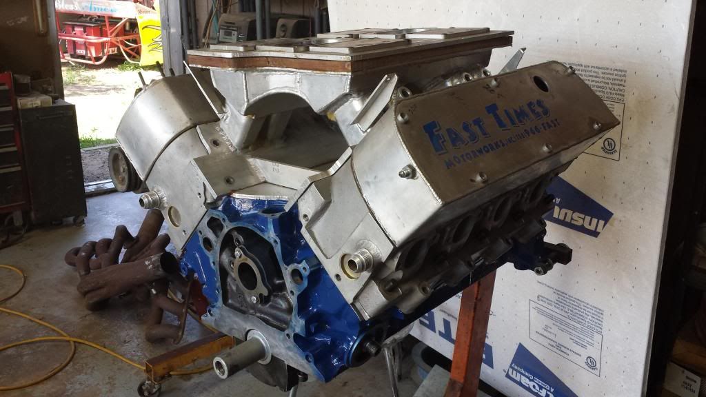
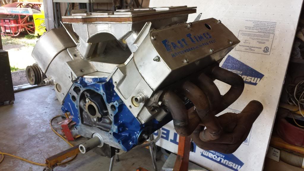
Anyhow, this is where it sits. Tomorrow I’ll be pulling the 351 out, and cleaning the engine compartment. If it needs resprayed I’ll go ahead and do that too…but it actually looks pretty well done…just dirty.

More pictures to come!

Thanks for that Randy! I’ll try to post up some good pictures tomorrow. There’s a LOT off the car, lol.

I’ll also take a look and see if there’s any differences in my two grill sections. I will say though, the old one was so messed up that unless the new one is blatantly wrong…its going to be a tremendous improvement, lol.

You need to look at the center upper mounting tab, where the grille section bolts to the body colored center grille piece. The early 67s have an open cut out area which was prone to cracking due to a lack of support. To “fix” this the later 67s have a bit of a bridge crossing this area. In 68 this bridge got even bigger, close to double in size. When you see all the different designs together it is very easy to see the differences. With the hood closed you cannot see the area that is different, the hood must be opened to see it.

Randy Goodling
CCOA #95

Soooo, things just got accelerated a bit. The 302/High Port motor has been cancelled in favor of a 347 that I picked up for a steal. In an odd twist it turns out I actually built the motor a number of years ago, and the only change has been a rebuild with .010" larger pistons, and a freshening of the heads. The cam was an N/A grind with light N20 being a possibility, so I know it’ll work 100% fine in my N/A application.

This thing was built for a wee bit of rpm :slight_smile:.

Anyhow, here’s a video of it idling after the rebuild. It hasn’t been run in a car since it was freshened.

https://www.youtube.com/watch?v=j7fEiU1egjs

https://www.youtube.com/watch?v=j7fEiU1egjs&list=UUYaBZWOh1BDPilsDYi7TH7g&feature=share

Is there actually a way to embed the video?? I’ve seen others do it but I can’t seem to figure it out. (Admin: Use the YouTube button in the tool bar and eliminate everything but the ID)

Anyhow, the main reasons for the change in direction are simple. This entire longblock cost me only slightly more than the 225cc High Ports and a matched intake would have by themselves. The motor makes plenty of power…enough to push a working 3000lb car into the 10’s anyhow…which is my current goal. The Canfields on this motor are basically little brothers to the High Port, with very similar valve spacing (NOT STOCK), and a slightly less elevated exhaust port. The only real drawback to them is they’re only 198cc, versus 225. Also, since I’m not constrained by the smaller displacement, when I DO pick up new High Ports, I can go straight for the 240cc version for a couple hundred more than the 225’s. As I said in the video notes…money saved and value gained!

Just thought I’d share :slight_smile:.

Thank you to the admin that corrected the video for me…I very much appreciate it.

So, on to the project!

Over the last weekend I only had one day of clear weather, thanks to the storm that came up from the pacific :l. Anyhow, I used it to good advantage by pulling the 351, and looking to see what condition the engine compartment was in. Luckily, other than being a bit dirty…all seems well. There’s a few things I’ll need to address…but for the most part it looks good.

That’s that…relatively solid if you ask me. The 351 appears to actually have been rebuilt, thankfully. Ohh, also…does anyone want to trade my power steering setup, for their manual? It seems a shame to spend $50 on the servo delete deal…when I could possibly just pick up a manual setup from someone in need of power assist.

Now, on to more motor fun!!

The shortblock arrived today. Looks a lot like it did when I shipped it out years ago, lol. Well, other than someone painted over my beautiful Ford blue with barbecue silver, of all colors, lol. Heads, cam, lifters, stud girdles, and valve covers should be here by next week at the latest.

Here’s some pictures!

This bottom end is SOLID. A4 block (the father of the venerable R302…look at those mains!), GRP aluminum 5.4" rods, and Ross XL400 Ultralight pistons. She spins pretty easily, if I do say so myself!

Flat tops cut for High Port/Canfield valve spacing. I will never, ever…willingly use an AFR, Edelbrock, or any other stock valve placement cylinder head by choice. The main downfall of the Windsor cylinder head architecture is that the intake is slammed up against the cylinder wall. It doesn’t matter HOW good the port is, if 35% or better of your intake valve is shrouded by cylinder wall…you’re losing air flow and power. Back in the day, TFS addressed this with the High Port (which had like umpteen patents on it), by moving the intake valve INWARD towards the center of the bore, and the exhaust valve outward towards the cylinder wall. They also shortened the intake port, and raised the exhaust port. Suddenly, whole new worlds of power were available to small block Ford enthusiasts. The Canfields are basically a copy of the High Port (there was a pretty serious law suit over the whole deal, and Canfield settled by paying royalties on every head they sold), with a slightly less raised exhaust. TFS hit another home run with the twisted wedge stuff, by altering not only the valve placement (twisted and centered intake valve), but the valve angle also. The Canfields and High Ports however…are still an inline head. This is why, no matter how good the port on an AFR or Edelbrock head may be…it’ll never do what even a mediocre port on a High Port/Canfield does.

Speaking of Canfield…

These heads made over 550hp on pump gas (at a touch under 11:1 compression), with a tiny 2.02 valve…on the above 347. They are very good heads even out of the box. That’s gasket is the same size as a 1262 Fel Pro intake gasket…which is bigger than a Victor Jr runner at the cylinder head.

Gotta have Motorsports valve covers :slight_smile:.

So there’s we are. My next order of business is to clean the engine compartment, address what needs addressed, and mock up an old bare 289 block I have with the transmission using the stock motor mounts. I’ll take some pictures, make some notes, and leave a few marks on the shock towers and firewall so I know where things are supposed to be…then when the heads come in I’ll begin fitment of the heads, headers, and motor without the motor mounts. The goal will be to move the motor back an inch or so, and lower it a half inch as well. At that point I’ll order the mid plate…fit it to the block assembly, and mark out where it goes against the frame rails. After that, a tiny bit of fabrication…and the motor will be in and set.


So, I got some more time today with the Cougar. I decided (like yesterday…) to spend it working on getting the pedals converted over to manual, as well as converting the old style z-bar setup to cable. I actually did this exact swap once on my last Mustang, and assumed (wrongly), that it would involve the exact same process. This would allow me to perform some of the steps out of order, since I’d previously figured it allllll out.

Shoulda known better…lol.

Anyhow, on to the pictures.

I started out by dressing the top of the manual pedal in preparation for having a roughly 3" structural (read: mild) steel extension welded onto it.

Here is said extension. Its actually just a piece of flat concrete stake cut down and dressed up a little. I always keep a few spares of the flat stakes around as they’re a cheap source of mild steel for fabricating, guards for knives I make, and various other odds and ends. They can be forged/cut/welded into just about anything I might need.

Backed and trued to the clutch pedal in preparation for joining. I actually took it all apart again and widened the v between the pieces before I welded it.

Welded up, painted, and contoured to fit the cowl area, or so I thought. Turns out that either the pedal hanger on this car is completely different, or the under side of the cowl is. I ended up test fitting it like ten times, and regrinding about 3/4" off the pedal extension in the process. It fits now, but it was a hell of a piece of work doing it. Also pictured is one of THREE nuts I had to tack onto the pedal bracket. Apparently someone had twisted off all but one of the pot metal ones. Lucky me lol.

Roller bearing kit. Last time I used Mustang Steve’s deal…but this kit from CJ Ponyparts (sourced from the Mustang Service Center a mile from my house) seemed to work nicely also. The main differences seem to be in the amount of support provided by the setup, the fact that this one uses the pedal shaft as the inner race for the bearing, and that this one also requires no fabrication skills (other than basic grinder work to remove the old pot metal bushings). The Mustang Steve kit is as much superior to this kit, as this kit is to the stock setup. Maybe in another 40yrs I’ll have to rebuild the hanger bracket again lol. I’ll be sure to use Steve’s then =p.

Three pedals in the car…JUST like they should be! On a side note…this was a much more enjoyable process on the 68 (other than the repeated refitting), simply because the steering column was so easily removable. Getting that bracket and pedals in and out of a 67 is a rabid B!%*#!! with the column in place.

Speaking of the column…while it was out I took the time to sand down the primer and shoot it (and a few other loose parts laying around) with a nice satin black. I’ve decided this will be the main color for my interior, with gloss accents where applicable.

Anyhow, back to the clutch setup. I drilled a 1/4" hole at the upper rear (towards the driver) portion of the pedal extension…pushed a grade 8 stainless allen head through, and attached it to a 1/4" female rod end that I’d modified the clutch cable to fit. Basically I threaded the catch on the cable, and screwed the female rod end onto it with red Loctite.

This is the same type setup on my 67 Mustang, with a slightly different style rod end (captured ball). I went with a standard rod end this time for ease of fitment, and because that’s what my local supplier had in stock.

Pretty basic stuff :slight_smile:.

Now here’s a fun pair of pictures. The top one is the Mustang, bottom the Cougar. See any differences in where the cable is coming through the firewall? Yeah…me too. The extensions were EXACTLY the same length, and I actually had to grind some off this time around, as I mentioned. It’s a bit puzzling, and rather annoying, since I’d planned to simply use a 3/8" thick aluminum brace as pictured above on the Mustang. Now I’m going to have to fabricate a bracket (like the one pictured first above…only, less flimsy) in order to stand the cable off of the slope in the firewall above the master cylinder area.

Yay.

So there we have today’s pictures. Tomorrow I’ll probably see about fiddling up a bracket so I can close out the clutch cable part of our story here. If I have time, I may even fit a dummy block and T5 into the engine compartment in order to start getting some measurements on what’s going to go where…and whether this cable will fit without a stand to hold it off of the block plate. Last time I needed a stand in order to take up free length in the cable…which was just as well since it also stood it out through the driver’s side header and kept it from immediately melting it, lol.

Anyhow, more to come tomorrow hopefully!

Strong work!!Lookin good!!

Thanks man! I have to say I’m enjoying it…though I wish I didn’t have quite so much to do, lol. I think ‘fixing’ the exterior will be next winter’s project. I’ll get it all sanded down and basically smooth (and all one color lol) this year…and call that part that. The drivetrain fitment is going to be an epic all its own, and at that point I’ll need to drive it awhile to get up the motivation for the rest =p.

Oh, also…speaking of the drivetrain. Like I mentioned above, I fit the wheels with my 1.25" spacers. The driver’s side fit REALLY well…with the outside edge of the tire ending up about 1/2" inside the wheel lip (unrolled), which put it about an inch inside the outer wheel opening. The passenger side on the other hand…had issues. The outside edge of that tire was flush with the outer wheel opening, or even a bit past it. First thing I did was pull the rear end and check to make sure the spring perches were centered to the wheel mount faces, and they are. I then checked the springs, and they’re mounted securely (not to mention in an identical manner) to the perfect rear frame rails. Soooo…I dropped a plumb bob from the outer wheel opening (along the quarter panel so the string hung from the lip), and measured the distance to the leaf spring. There’s 7/8" difference between the two measurements!! I’m completely baffled…the car is completely unmolested as far as those wheel lips go. None of my Mustangs had this issue. I can’t for my life believe there was THAT big of a production tolerance on things like that either. I mean, all the inner wheel housing stuff measures out perfectly. The only thing that’s off is the quarter panel. Worse though, is I’m not sure what on earth I’m going to do about it. That much difference is unacceptable…and I really don’t want to run narrower wheels so I can rig up different sized spacers to make it work :l.

[quote=“CrisAnderson27”]Now here’s a fun pair of pictures. The top one is the Mustang, bottom the Cougar. See any differences in where the cable is coming through the firewall? Yeah…me too. The extensions were EXACTLY the same length, and I actually had to grind some off this time around, as I mentioned. It’s a bit puzzling, and rather annoying, since I’d planned to simply use a 3/8" thick aluminum brace as pictured above on the Mustang. Now I’m going to have to fabricate a bracket (like the one pictured first above…only, less flimsy) in order to stand the cable off of the slope in the firewall above the master cylinder area. /quote]

The Mustang is your 67? If so there are a lot of differences between 67 and 68. Things you would not even imagine that they would mess with have been changed. Same with the 69-70 Cougars. Sometimes I think that they changed things just for something to do.

Randy Goodling
CCOA #95

Yeah, I’ve come to that conclusion. I mean, I knew there were some differences…even a lot of them. But like you said…things you wouldn’t even imagine, lol.

So I finished up my clutch cable support bracket today. Loads of fun THAT was. In the end it didn’t turn out too badly, but I’m still slightly frustrated that I have to use it at all. I would have much preferred fitting an engine today…lol. Anyhow, here’s the pictures:

So this is what I started with. A dirty engine compartment/firewall, and a small sheet of 12ga steel I picked up at the local steel yard for $2. I only needed about 1/8 of it for my bracket, but I figured at that price…and with my current batting average…it’d be better to have LOTS of extra for multiple attempts. Thankfully, so far…only one piece was necessary.

I skipped a few steps here, but basically I cut a small section off…transferred the bolt hole locations from my pedal hanger (this wasn’t the best idea…the thing sort of flexes out when its not bolted in…but so far I’m making it work), drilled them, dressed the bracket, then put in the initial 90° bend. In the second and the last pictures you can see the measured and marked location of my second bend, as well as the initial mark showing where I’ll have to trim it for it to fit under the cowl flange.

Rough fit…still needed to locate and drill the clutch cable opening, as well as the master cylinder opening. The clutch opening I nailed…the master cylinder opening, I’m not so sure. See, the holes in my SVO master cylinder (I’ve used this on disc/disc conversions in the past with no issue…oh, wait…you’ve heard that before…go figure) don’t line up with the holes to mount my clutch hanger…they’re about 1/4" wide on each side. At first I attributed it to me welding the nuts on a bit wide…but then I got to looking at it, and that might account for a total of 1/8" per side. The thing is just flat too freakin wide. Soooo, that leads me to ask…is there a Cougar specific manual disc/disc master cylinder that I’m just unaware of? Or are you guys just making the SVO unit work? I’m thinking that if I have to I can elongate the holes in the car, along with the holes in my plate, and then ‘clamp’ the lower part of the pedal hanger bracket until it lines up with the master cylinder holes. It’s not the way I’d prefer to do it…but I’m not about to do major surgery on anything to get a $20 part to fit.

Roughly finished bracket with a coat of paint on it. Tomorrow I’ll finish up the fitment…dress all the edges, and hit it with a couple more coats before mounting it permanently.

So that’s that. I’ve got to say this was a hell of a lot easier on the Mustang!

Oh, also…one quick question for you guys. I live about a mile away from an early Mustang garage called ‘The Mustang Service Center’. They stock these black ABS plastic ‘cowl repair’ kits exactly like the one above from WCCC. I guess basically you gob the upper part of the flange with the sealant, slip it up into the existing cowl vent…and screw it in with some kind of self tapper. My questions is…is this any really effective repair? Mine seem to be rusty, but not excessively so…although they do leak. I also have that Sikaflex A1 which is far, far superior to typical automotive sealants. Anyhow, I’m just wondering if any of you have used them and actually had some success. I know for a fact that I’m not cutting off the cowl to weld in new vents, regardless…so I’m hoping at least some of you answer yes =p.

Weeellll…turns out my cowl vents aren’t leaking (that I can tell). I ran about a gallon of water down the cowl. All of it seems to have blown out the drains beneath the fenders. There’s nada inside my car…so I must have got some in the holes in the firewall previously while testing.

Hurray for small miracles, lol.

Anyhow, I got my bracket mostly completed (turns out I needed to relieve it for the master cylinder lol). It still needs dressed up some, but I’m happy with it otherwise. It’s 100% functional as/is. Also, squeezing the bottom of the pedal hanger bracket together worked just fine for mounting the setup. Sucks to have to do it…but at least it worked.

So…it turns out that the pushrod for the SVO master cylinder is about 1.5" too long. Lopping off the required amount, threading it…and using an all thread coupler solved that issue. It also allows me to adjust it a bit, which will allow me to even out the pedals if I so choose.

Mocked up in the car. Nice to finally have something actually functioning as its supposed to!..lol.

Anyhow, I was going to pull the ac/heater assembly today…but as the cowl vent doesn’t appear to be leaking…I’m debating that. I think I will end up pulling it anyhow prior to hooking up the heater (won’t need THAT until next winter, lol)…and I don’t know if the car will get AC this summer either. That may just end up one of those projects for next year…and I may go with a whole new Vintage Air GenIV system while I’m at it, lol.

So next I think I’m going to start messing with getting the other parts of the interior cleaned up and painted (mostly the dash). I still need to go through and sort my chrome so I can get pictures of it for you guys too. The motor and trans still need mocked up as well…but I need my heads for that, which won’t be here till next week.

So that’s that for today. If I manage to get anything else accomplished this weekend I’ll be sure to post up some pictures, lol.

Sooo…with the clutch, brakes, and whatnot straightened out…I decided to get some of the work done on the front end. Namely, removing the vacuum setup, cleaning and repairing everything that needed repaired, and installing the electric headlight door kit (nothing but GREAT things to say about that kit btw). Everything started out smoothly enough, I got the passenger side all apart and cleaned up easily. When I moved to the driver’s side however…that all changed lol. Apparently the car had been dinged somehow in the driver’s side fender, behind the extension. I knew there had been damage there (lots of ripples from an attempt to straighten)…but I didn’t realize they’d removed the front inner fender support. You know…the bucket looking part of the fender that the headlight housing bolts to. They’d split it at the spot welds (amazingly it was in my box of parts, and they didn’t destroy it in the process) so they could straighten (I use that term loosely) the fender. So, I lined everything up, clamped it down…and tacked it back in. It’s rough, mostly because the fender is irreparable (at my level of bodywork skill anyhow)…but it sort of fits in with the ‘resurrected junkyard dog’ theme the exterior has going on, lol. Later I’m planning on going with glass fenders anyhow…so I didn’t want to spend incredible amounts of effort on this.

Anyhow, on to the pictures!

This was the work I’d finished the day before yesterday. I think it turned out pretty nicely myself.

This isn’t exactly the proper way to fix this…but they bent the fender flanges all to hell when they separated it from the support bucket. Sooo, I got it back to a serviceable fit, lined everything up, tacked it down, and painted it.

Headlight bucket fit perfectly.

I can’t say enough about this kit. It IS a bit pricey (I opted for $350 used motor kit, as $535 was a bit out of my budget)…and I probably could have fabbed my own up…but having the headache of fitment, and making it work all taken away was worth the price. I believe Don sells the kit with the remanufactured motors on the WCCC site. I honestly don’t think I’d have enjoyed drilling that single hole with the grill assembly still hanging in there, but I’m sure its totally doable, lol.

Got the engine compartment mostly cleaned up and sprayed.

I also sprayed the grill. The paint that I’m using is a satin, with a self etching primer built in. Pretty cool stuff. Once the paint’s set, I’ll go back through with a towel and acetone, and remove it on the large chrome stripes.

It’s starting to look like a car!!

Anyhow, to finish things up, I fixed the two tiny cracks in the passenger side headlight assembly (JB Weld is wonderful stuff, lol). It should set tomorrow, so I’ll get down to finishing paining that grill, and give them a few days for the paint to cure so I can get the chrome cleaned up. I’ve found that’s the trick to keeping the paint from flaking through that whole process. I’ll be sure to get some pictures up when they’re finished though :slight_smile:.

If I were doing my headlight grilles over, I’d leave them all blacked out. Just sayin’!!!

Looks great that way, IMO.

I was thinking about it…but with the car being completely satin black…I think it would make it look like I just dipped it in paint. I’ve always hated that look…the kids around here call it ‘murdered out’ lol, and to me it just looks like someone painted the entire car without bothering to mask anything. If the car were going to stay grey primer, or any color (even gloss black), I’d do it though. I was actually surprised how much I love how the look of them blacked out like that myself! As it stands…I’m keeping the grill (I’m doing much more black than the factory though) window molding, drip rails, XR-7 badges, and maybe the Mercury and Cougar badging. Since I’m also eventually smoothing the fenders ala 67 (or rather, not punching the holes in the glass fenders lol)…I may put the ribs in front of the rear wheelwell also (I loved those on my first car!!). The wheels will be bright as well, and I’ll probably do the tail lights like the grill…satin except for the top of the ribs.

I’ll say this…seeing it slowly becoming a car again is really making me want to drive it. Sucks because I know I’m still at minimum, MONTHS away from that…/sigh!

Ah. Thought about asking what color you were going with. That may be a bit too much black, then. :shrug:

Keep it up, you’ll get there!

Quick little update. I spent some time doing a quick and dirty resto on my tail lights. Basically I just separated the housing, cleaned everything, buffed the lenses, scuffed/sanded all the chipped areas of the chrome, and repainted them. For the short term this will have to do. Like I said…I need to get the car moving, lol. Once that’s done, I’ll go back and revisit sections of the car at a time. I know that sounds backwards as it’s ‘easier’ while everything’s apart, but I genuinely hate having a project around that I can’t drive within a reasonable period of time.

Anyhow, I’m pretty happy with how it turned out…here’s a couple pictures.

Not too bad. 100% better than the way they were (hopefully you can tell which I had already finished lol).

On the car.

Quick question? The last Cougar I messed with was literally 20yrs ago. Are all the fuel filler openings this far offset?? I mean…this thing is set over an inch to the passenger side of the car. Obviously Mustangs are centered, and I can’t for the life of me imagine why they’d offset it on purpose. Is this just one more thing that they changed for no apparent reason, lol?

Here’s a question for you all!

Anyone care to guess what cylinder heads these are?

:slight_smile:

Yates or Canfield?

Yates are canted…these are rotated around the bore centerline.

But more importantly…did you notice the intake port locations??

:wink: :laughing:

Oh, I forgot to add these! The heads on the left are Canfields (for comparison sake). On the right are these heads.