70 XR7 ammeter wiring harness question that maybe Midlife (or others) can help with:
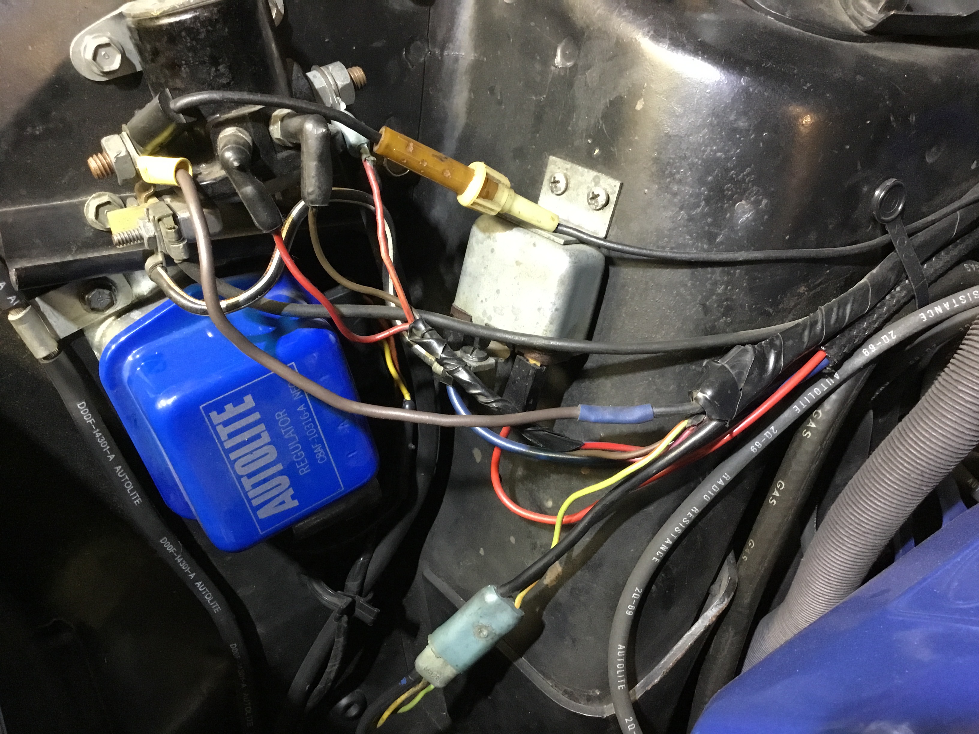
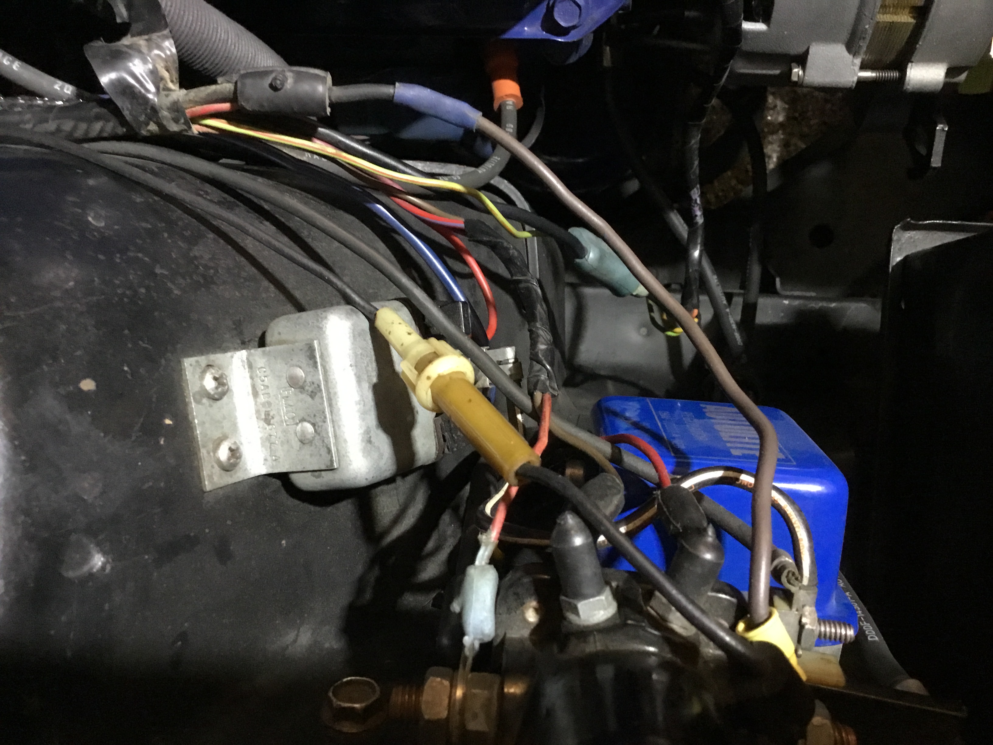
I can see where the heavy black alternator output (38 on the schematic) goes from the blue alternator plug into the harness by the shock tower. Then up closer to the firewall, it appears to loop back and exit from the harness in the same location by the shock tower. I think this loop of wire 38 forms the ammeter shunt?
Heavy black wire 38 exits the harness and turns to heavy brown at a blue splice, then connects to the battery post on the starter solenoid through a yellow ring terminal.
What I am confused about is where do the ammeter wires (yellow 654 and red 655 on the schematic) tie into the 38 loop? I assumed one would attach where 38 loops back in the harness, and the other would attach at that blue splice or at the solenoid battery post. But I don’t see them.
Red ammeter wire ties into the splice of the fusible link (goes to starter solenoid) and battery power line; yellow ammeter wire ties into the splice closer to the firewall that joins main power line with line coming from alternator.
Thanks Midlife! So is the fusible link buried in the harness, or visible? I suspect this brown section with yellow ring terminal might be spliced in by previous owner, and they might have failed to hook the ammeter leads back up. There are signs that a battery blew up in the past.
OK, I see what has happened now. Red ammeter wire is properly tied into the factory fusible link splice. But previous owner has replaced a burned out fusible link with the brown wire. I think I can just splice in the proper fusible link and be done. Guess I’ll have to crimp it since soldering would melt the fusible link?
Just for my own curiosity, are you sure that is a fusible link wire?
Neither the shop manual nor the wiring diagram for 1970 shows a fusible link wire.
It does apply for 1969 however. (convertible top)
The wiring diagram does show the red & yellow amp wiring
spliced in as Midlife mentioned.
In any case I would investigate and see what caused the “melt down”
As best as I can determine, the purpose of the fusible link is to protect the battery from excessive current from the alternator. If you want to keep it factory correct, replace the non-fusible link with one from NAPA (14 gauge). I will say, however, that replacing the factory OEM splice with a butt splice is a royal pain.but so is soldering it.
I wasn’t sure if the 70 cars had a fusible link either - Midlife to the rescue! I won’t try to replace the factory splice block where the red ammeter wire joins, assuming I can manage a solder or crimp butt joint to the fusible link wire where the blue splice is.
My convertible top takes power from after the power window circuit breaker, so doesn’t have that fusible link even though one is shown in the schematic.
Fusible links are there mainly to protect the rest of the wiring from overheating and starting a fire. Mine apparently did its job many years ago.
The battery, alternator, and regulator have all been replaced since then and are working great, so I won’t have to investigate. But there was paint damage on the engine and hood bottom from an exploding battery many years ago. I imagine that is when the fusible link got replaced by the brown wire.