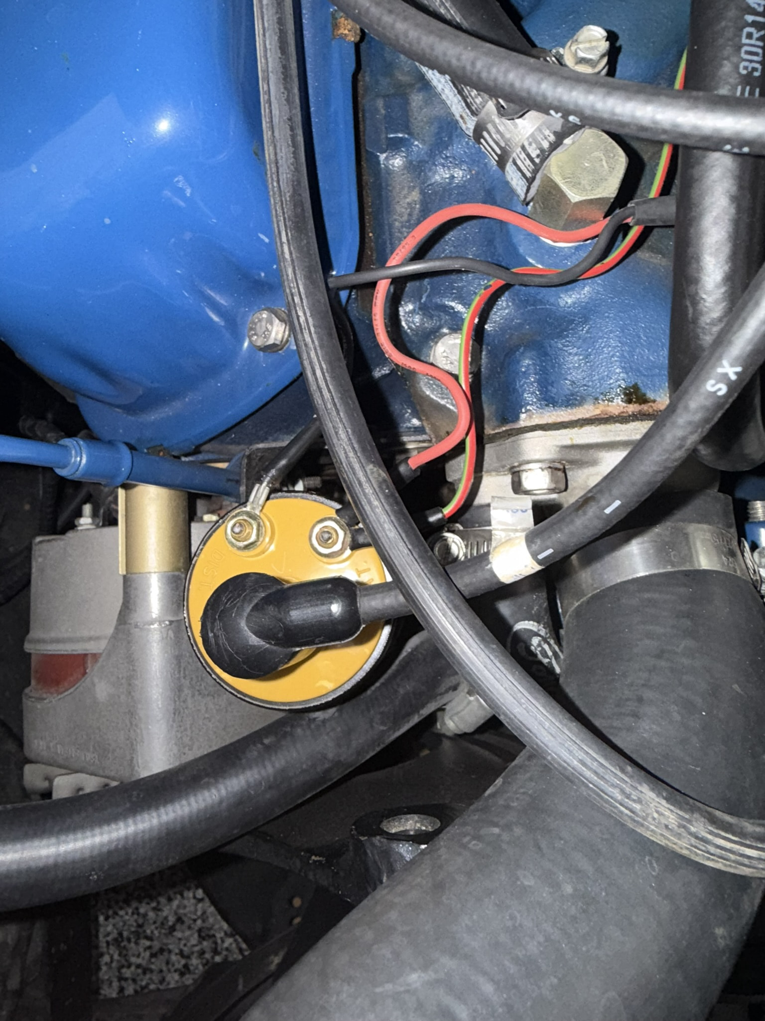
When the engine is running I am getting battery voltage to the coil. There is a Pertronix module in the distributor that I believe needs 12 volts but the coil does not. I think the coil could be overheating and causing the car to stall. I found an electrical item in the glove box that may reduce the voltage to the coil but I don’t know what hooks up where. The black wire and the red wire come out of the distributor, the red/yellow from the wiring harness.
I hope my question makes sense. Any information as to if this is the right part or what I should do next is appreciated…
Assuming you are using the factory yellow top coil, it is designed for full battery voltage only when cranking the starter. So you are correct that full battery voltage when running is too much and it will overheat. The factory yellow top coil needs to be fed by the factory pink resistor wire (assuming it is intact), or through a ballast resistor if tied direct to battery voltage. Or you can replace the coil with one designed to be powered directly from battery voltage. Lots of discussion on the different options with Pertronix ignition here:
a. Disconnect the battery NEGATIVE (ground) cable.
b. Turn the ignition switch to the “ON” position.
c. Set your DMM to the OHMS scale.
d. Place one lead on the battery POSITIVE terminal.
e. Place the other lead on the coil+ post.
If you get a reading of less than 0.5 Ohms your resistance wire has been bypassed.
If you get a reading between 0.5 and 1.0 Ohms +/- your resistance wire has been bypassed, shortened or you have poor connections between the battery positive and ignition switch or ignition switch and coil.
If you get a reading between 1.0 and 2.0 Ohms your resistance wire is still in place.
If you get a reading of 2.0 Ohms or more, you have unusually high resistance and all connections should be checked.
Method “B”
a. Set your DMM to DC Volts. Measure and record battery voltage.
b. Place the RED lead on the battery POSITIVE terminal.
d. Turn the ignition key to the “ON” position.
e. Connect the BLACK lead to the coil- post.
f. MOMENTARILY connect a jumper from the coil- post to a good ground and record the voltage reading. Don’t leave the jumper connected for more than a few seconds.
g. Subtract the voltage recorded in “f” from that recorded in “a”. That is your coil supply voltage. Note that this includes the resistance of the coil primary winding. With a 1.5 Ohm coil installed a voltage of 6vDC +/- indicates the resistance wire is still in place. A voltage of 9.3vDC +/- would indicate the resistance wire has been bypassed. Using an ignition coil of different primary resistance will affect the readings.
BTW - That relay in your first picture looks like a Pertronix unit that gets B+ to the Pertronix module. I am not a fan of those due to it’s lack of a fail safe that will allow the engine to run if that fuse blows or the relay fails. IMO it’s a cheap, poor design.
Actually that is my relay. I am not sure how it could function (fail safe?) any differently from any other relay. Two design exceptions pull down voltage is a bit lower to be sure that it stays latched under low voltage conditions, and an inline fuse to protect the power wire. So far zero failures in the field. Your Pedapter is a better product that is far more versatile, but also a great deal more expensive.
Sorry, Bill. I thought that was one of the Pertronix units I had looked at while deciding whether or not to build mine. Theirs was not sealed (not weather-proof) and was an on/off relay so no power to relay = no power to coil. Knowing you I am sure that yours addresses those shortcomings.