I searched for “engine detailing” under the above heading as I was advised to do by a gentleman at WCCC and found 110 matches, but I did not see any that mentioned the 351C in a 1970 Cougar or Cougar Eliminator. I realize that I might have missed it, so if that is the case, then please direct me to the correct topic and discussion. I am replacing the generic pats with the correct heater hose, clamps, both radiator hoses, etc obtained from Marti Auto Works. Also installing the correct battery cables and starter cable set from NPD. I have previously installed the correct blue metal “heater hose” tube along the passenger side valve cover.
My main questions at this time are:
Heater hose routing: Which heater hose connects to which heater core tube that passes through the firewall (my car is an A/C car)?
Which heater hose has the heater control valve in it?
Where does the bracket with grommet (part number BC-10 from Marti Auto Works) for the starter cable attach to the engine or engine mount?
On the starter cable tab with the hole in it: Does that tab attach to the bottom bolt on the voltage regulator or somewhere else?
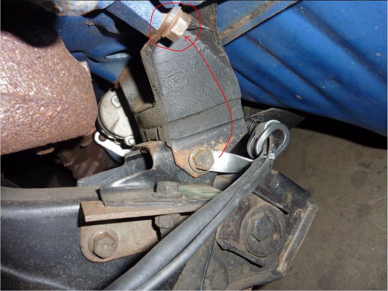
This is what I have for the small block starter cable mounting. I’ve been told that this image shows an incorrect mounting location, and that it should be mounted to the upper bolt at the block (red arrow and circle in the pic). I don’t know for sure if this is true or not, but I bet folks here will clarify. I’m also not sure if the 351 should use one clamp, or two though.
*I did have a recent experience replacing motor mounts and starter cable on a 351C car. I found that using two clamps was kinda cumbersome in that area, and that mounting the clamp to the lower bolt seemed to keep the cable further away from any heat sources, like the block itself.
I must have been timed out during the time that I was writing a reply to this and doing other things. So very frustrating, because I did not copy what I had written…major double bummer!!
I do thank everyone for your replies above. I noticed that page 34-04-41(and the diagram above from that same page?) do NOT show a 351C but only the 2 and 4 bbl 351W. So I went searching one more time in this Maintenance Restoration and Repair for “heater hose routing 351C.” That is when I found a posting from bsbeck on 15 August 2018 titled “Heater hose routing for 351C without A/C” located at https://cccforum.discoursehosting.net/t/help-heater-hose-routing-for-351c-without-a-c/9428/1 badcatt posted photos of his 4V 351C. His first photo shows both heater hoses running along the intake side of the passenger side valve cover. badcatt’s second photo shows the heater hose with the metal tube and the heater water control valve running closest to the passenger side valve cover. He also notes that the hose [without the water control valve] “is inserted in a clip on the choke housing” and then that hose drops down across the back of the valve cover. I am assuming that same hose [without the water control valve] attaches to the heater core tube that is to the left (as viewed from the front of the engine) of the other (right) heater core tube which must be the inlet tube based on info in this posting and on the 15 August 2018 posting.
Therefore, my question #2 has been answered!! Thanks!!! Please correct me if I have misunderstood.
However, I remain confused where the Inlet heater hose attaches at the front of the engine. One hose is attached to a fitting on the water pump, and the other attaches to a fitting behind the water pump (and a little lower) on the engine. Which one is the inlet hose to be connected to? The answer to that will finish answering my question #1.
The answer to Question #3. seems to be that the bracket should be attached to the bolt at the front of the motor mount, is that correct? Also, is the starter cable to be routed between the motor mount and the engine block?
Regarding Question #4., I have attached the ground cable (with the tab which has a hole in it) to the bottom bolt on the voltage regulator from what I have understood.
Starter cable bracket attaches typically to the forward motor mount to block as you suspect and the cable runs through that bracket and straight back between the rubber engine mount and the block to the starter. Would also have had an asbestos outer protective sleeve on the cable in this part of the cable
Believe there is a hard line/tube that the heater hoses connect to and runs the majority of the length down the passenger side of the engine compartment. Just like small blocks used in 70. Not the same part number though I believe.
This would be a single tub rather than the double style used on some Boss 302’s.
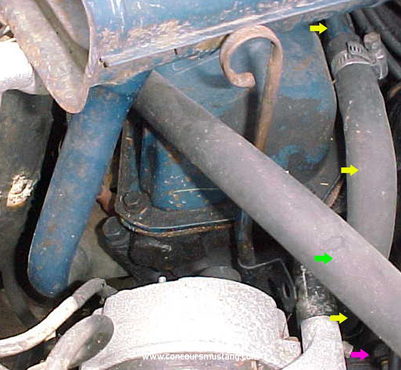
The heater core connection to the inside/center of the car is the one that attaches to the control valve and in turn is connected to the tube. At the front that hose (Yellow arrow) appears to be routed down behind the water pump and to the outside (passenger side) of the sender (purple arrow) .
Green arrow hose would have been shorter (been replaced) and routed over the metal tube between the intake and valve cover
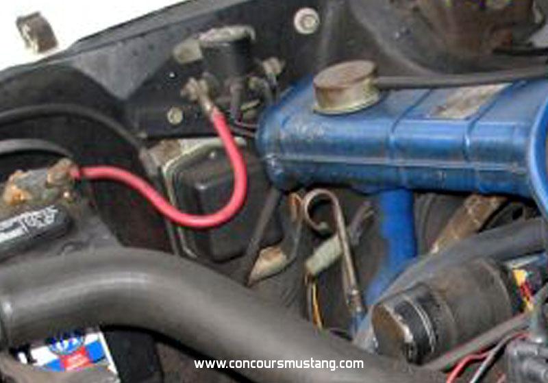
As Mike offered there is a thread over on the Councours site that might be useful. Pictures are a bit rough but not allot of pictures were available but it does show some of the details that may help you. Hope its ok to cross post to help you out. IF not Moderator please delete Pictures do include non-factory hardware and other parts you need to ignore
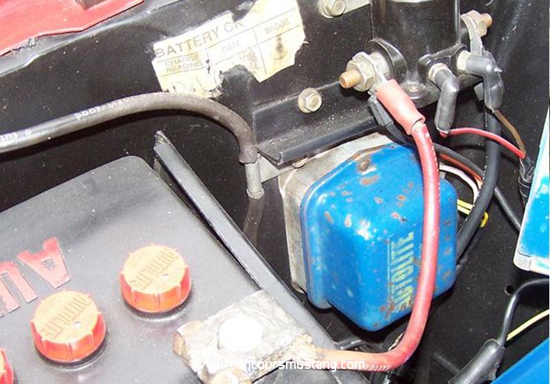
For the grounding of the starter cable to the body (first year for this location and style) typically find 70 Dearborn workers installing them as shown in the picture of the unrestored examples below with the radio suppressor being attached to the lower voltage regulator screw
Thank you 3_Speegle!!! I appreciate your specific answers and the very helpful photos!!! I believe that what you have posted has answered the rest of my questions.