Being into the true essence of DIY car stuff, I’m working on my own flavor of headlight door electric conversion. I know that this has been done before but I have never seen a clear summary of everything in one place and anything even partially complete since 2010 or 2012 that would allow someone to roll-their-own solution. So….
I tried a while back to finalize a design based upon copying the GM torque/current limit sensing but I never was able to finalize this concept. Regardless it is not too DIY friendly as it requires circuit design and fabrication etc. I got close but decided to look at something simpler. If there are any combo sparky and car geeks out there, I can share what my circuit designs.
After reviewing the existing products and some history on this site and others, I am trying the following route. I will share everything here in this thread so that anyone an copy for free.
Initial parts list:
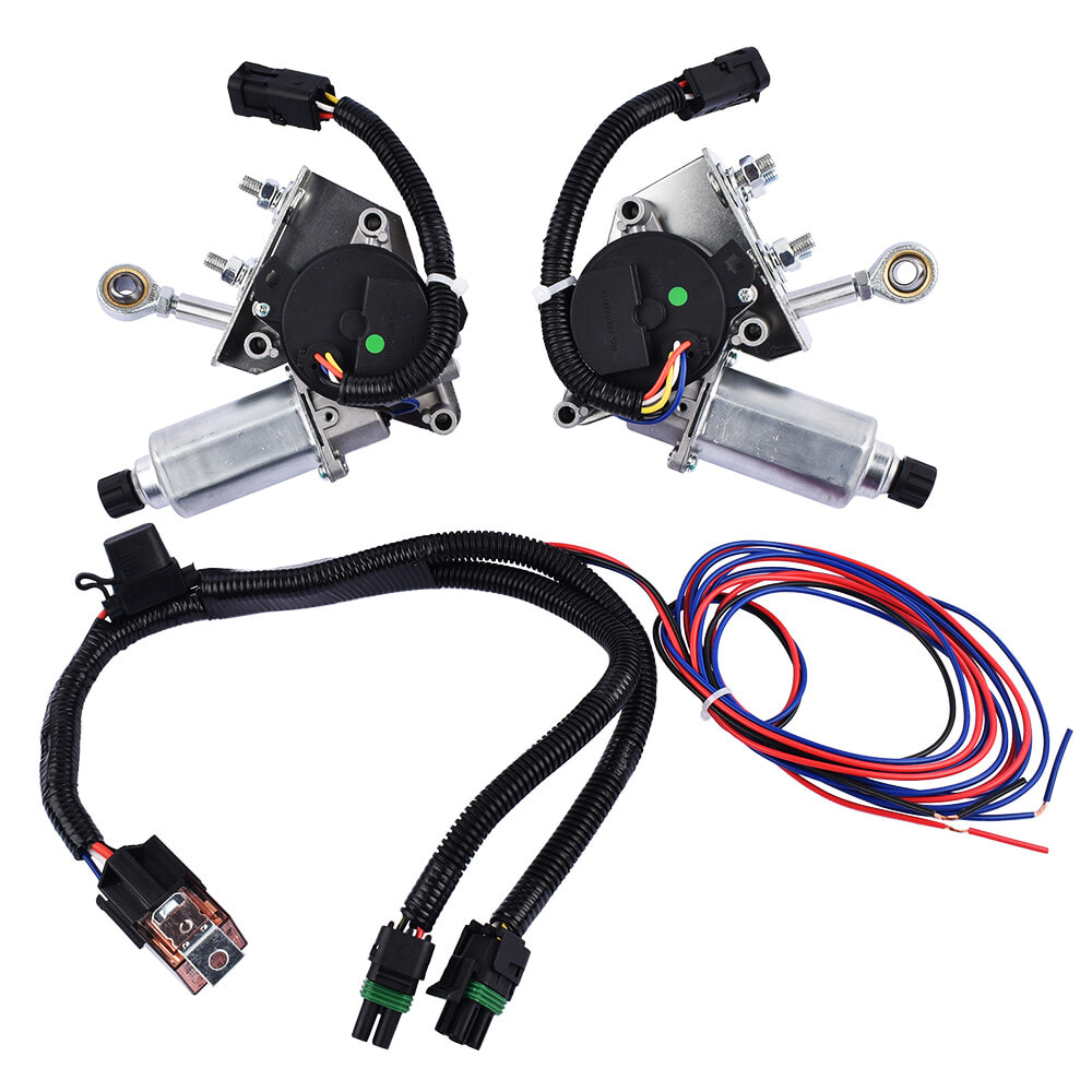
Miata/Ford style motors
Everybody appears to be using the same motor just slightly different paint or powder-coat and other small details and obviously different brackets. These motors include an internal rotary switch which controls the open/close positions.
I bought a kit designed for the Corvette simply because it was the least expensive, had good reviews and appears to have sold a lot.
< $100 with shipping. Shop around, the price can vary by 2X or more. Link below.
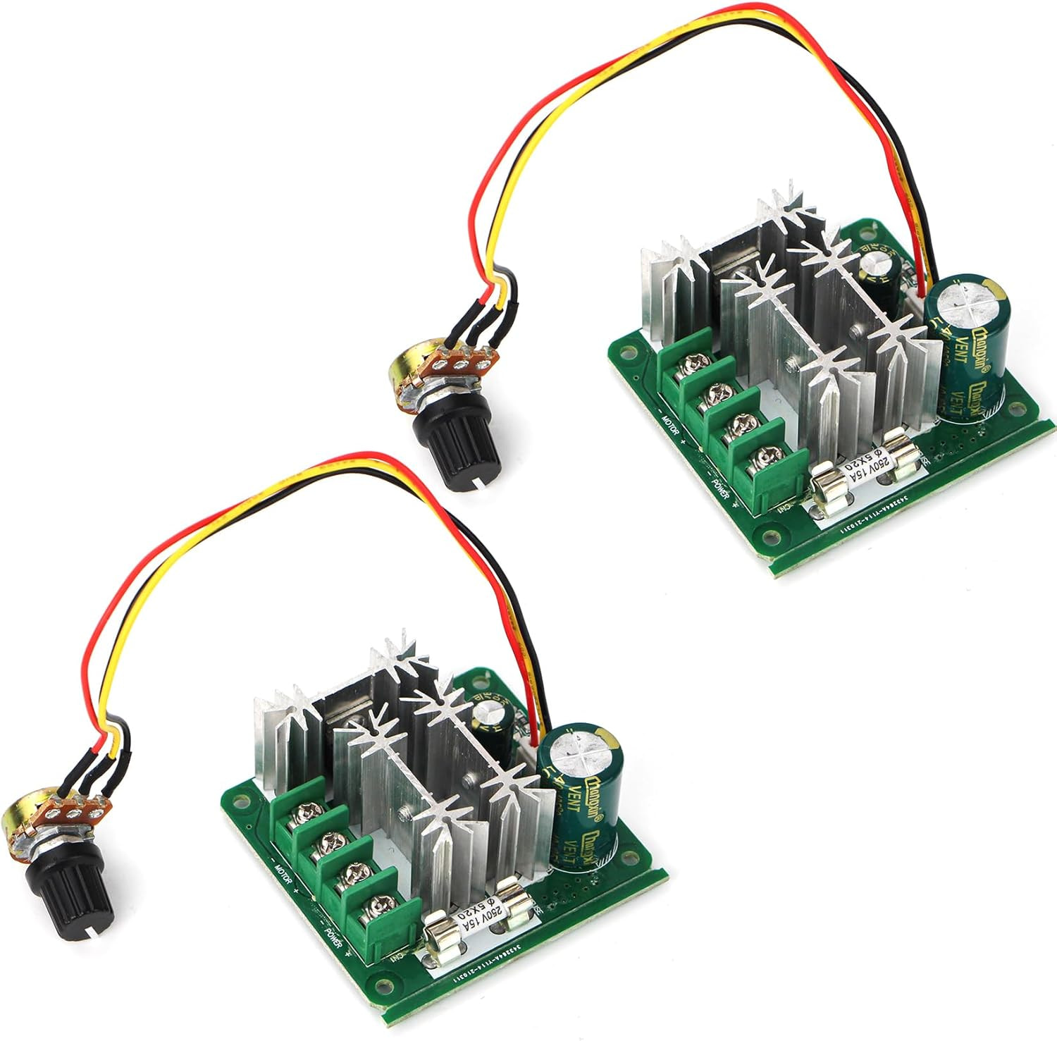
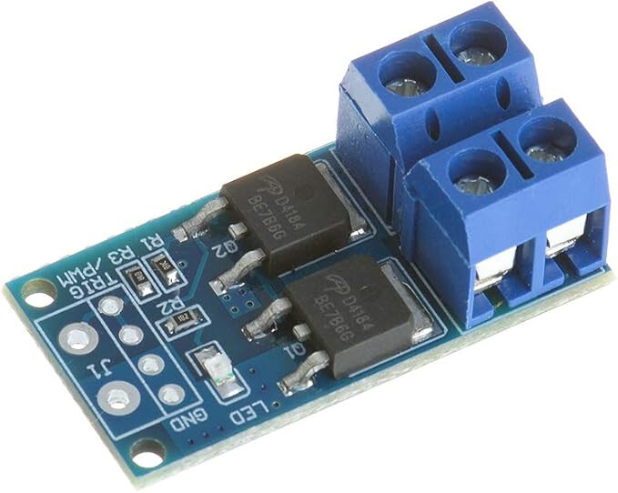
Lots of folks say that existing solutions are too fast to open/close. PWM = pulse-width-modulation basically turn it on/off at a specific rate to control how fast the spins.
15 A capable
~$15 with shipping. This is for 2X controller in case a fry one.
Imho the real key to this system is to build all the brackets, get them mounted and manually open the door and measure the total stroke required to cycle the door at the linkage mounting point. Now take the motor arm and redrill it to slightly less than half of the total stroke….may have to weld up existing hole.
Remove the springs and adjust the lids for correct position when closed by adjusting your heim linkage
When the doors are open , they should not touch the stop in either direction . Your old system was lazy vacuum that you drove into the stops….this is full mechanical that will destroy something if you allow it to hit the stops. Miatia motors mounted with the shaftsaimed to the rear and the override knobs kinda aimed at the radiator cap.
And yes they were fast , but you could reach over and flash someone before they got by you
I agree. Overall this is a pretty simple mechanical 4-bar linkage system just IMHO not clearly documented for the DIY person. The details will end up here in CAD for posterity.
FYI. What is a 4-bar link. Well see the link below. The headlight door system a rank and rocker style where the motor-arm is the crank and the headlight door is the rocker.
OK. Some really simple stuff first to keep you interested and me motivated.
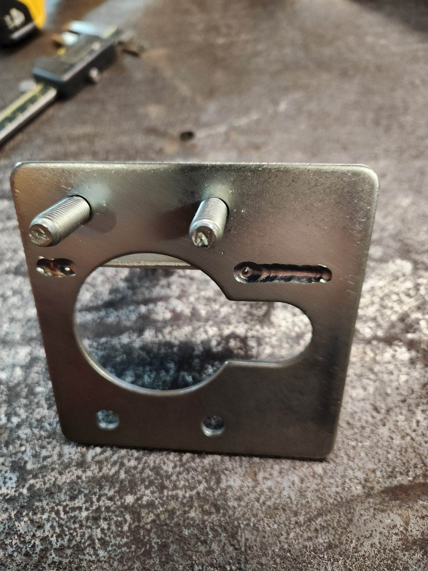
Remove mounting plates from motors. We will make the new motor mounting plates by modifying these plates. Why not? The holes are already there. The motor orientation is just all wrong but some welding will fix that.
Some ongoing reworking of the motor plate for the driver side. I’ll post a drawing when complete. Essentially, the Corvette mounts are upside-down compared to the Cougar. You will need some 12 gauge (2.5 mm) metal to make these mods.
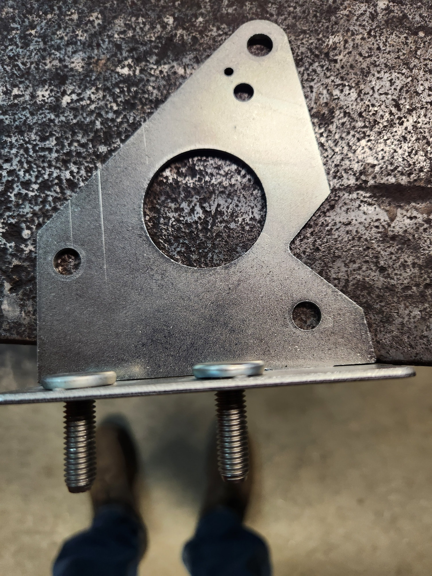
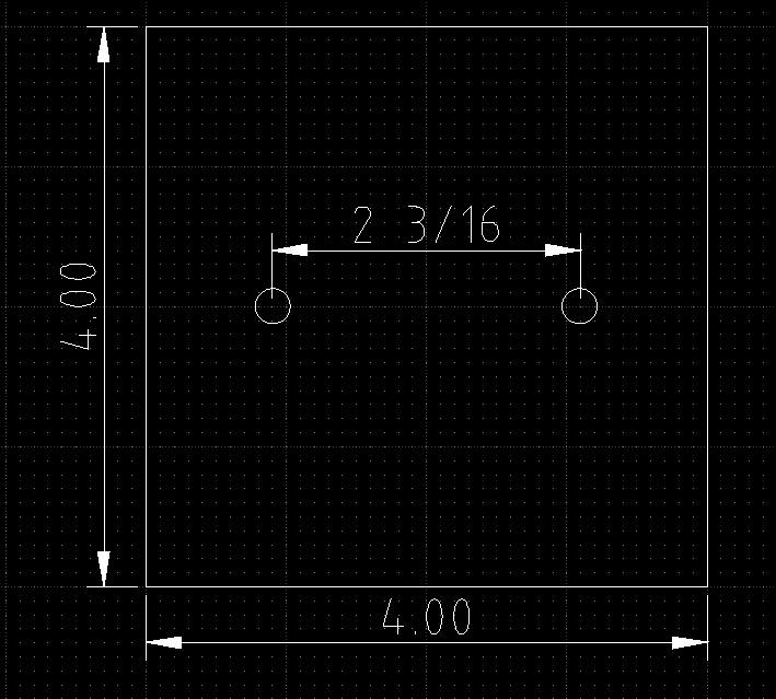
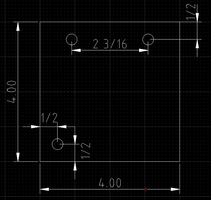
For the new baseplates, cut 2X pieces of 12 gauge (2.5 mm) metal into 4”x4” squares.
The hole patterns for the driver and passenger sides are different. I’m starting on the driver side for my 67. That baseplate requires 2X- 5/16” dia. mounting holes as shown below. The holes are symmetric off of the centerlines of the plate.
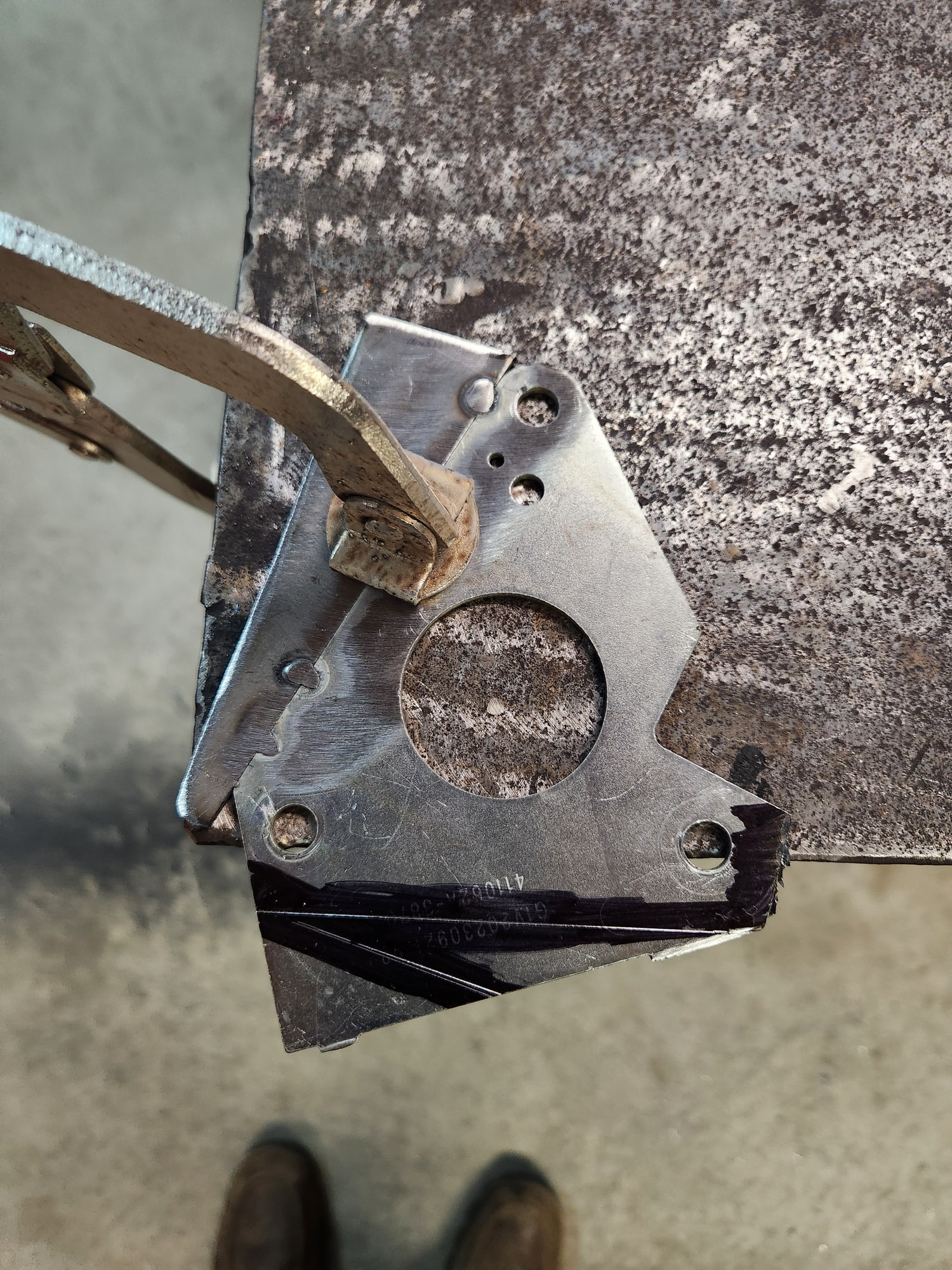
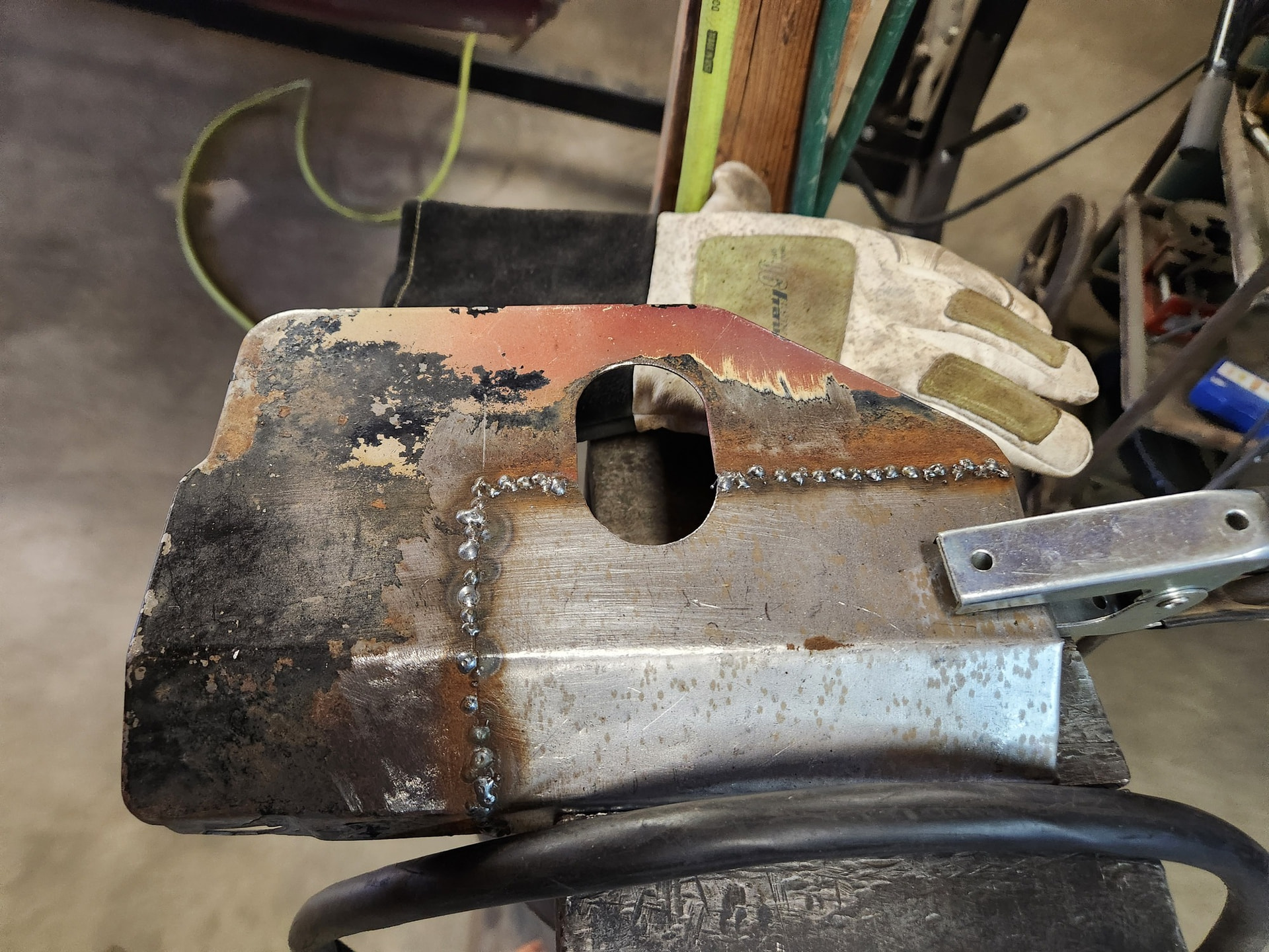
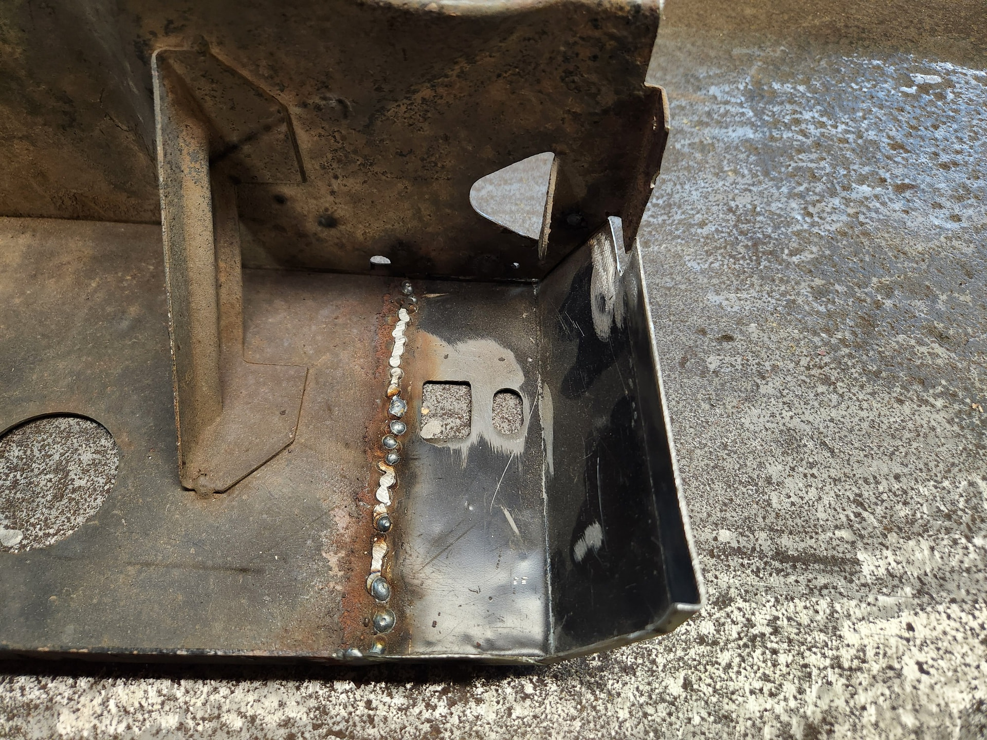
Working on the passenger side bucket today. When it was removed, it was “grade D” quality with some bad rot. Classic issue with 2 layers of metal and no protection in between. I had to rebuild the entire corner, but now it is patched up nicely. Just need to grind it out and weld back together. Then design the baseplate for this side.
Passenger side baseplate requires 3X 5/16” holes. The existing 2 in the bucket that are similar to those in the driver side bucket but are very far forward. This is definitely bad for stability of the motor assembly due to torque loading.
Some more engineering geekery required to truly understand this 4-bar linkage. Not 100% required but what is hotrodding without added serious mechanical engineering. It is obviously more fun than grinding.
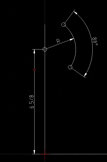
The headlight door does actually rotate almost 90 degrees (88 measured). Wow!
The center of the headlight door pivot is about 6 5/8” above the mounting surface.
The distance between the headlight door pivot and the connection point is ~1 15/16”
The vertical displacement of the connection point is ~2 11/16”.
The horizontal displacement of the connection point is ~ 1 5/8”.
Point-to-point the displacement of the connection point is ~ 2 3/4”
BTW, the crank arm on the kit is 1.5” c-to-c so looks like it may have to change. It appears a little too long unless there is a motor shaft position that allows us to compensate. The trick is to find a motor shaft location, heim link length, and crank arm length that work together.
That is my understanding. They appear to be the same motors as used on the “Cat Headlight” units as well as units for many other cars.
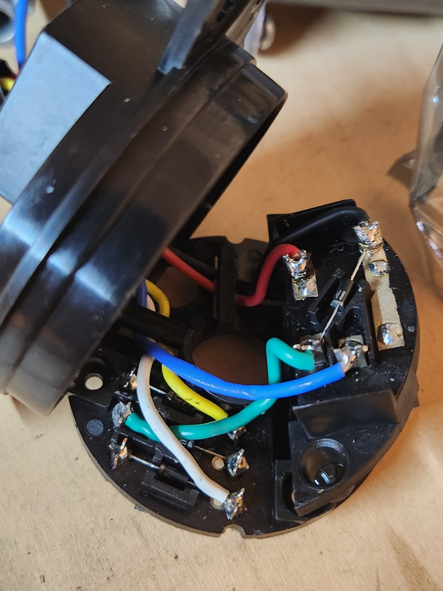
I just tore into one of the motors and was studying the internal switch and components. I did not expect an additional relay inside of each motor assembly. I was “ohming-out” the motor and saw unexpected values so a took it apart. Not sure if this is used in a latching relay configuration or not. I will work out the full circuit diagram soon.
Mechanically, I’d like to reverse the direction of the motor if possible for better characteristics (pull vs push) of the crank arm during opening. Electrically, the PWM circuit needs to ensure that the power to the internal relay remains correct. Interesting.
Would be a lot faster and easier to just buy but that is not my view of DIY hotrodding.
Just in case you have never disassembled your headlight conversion motors before….
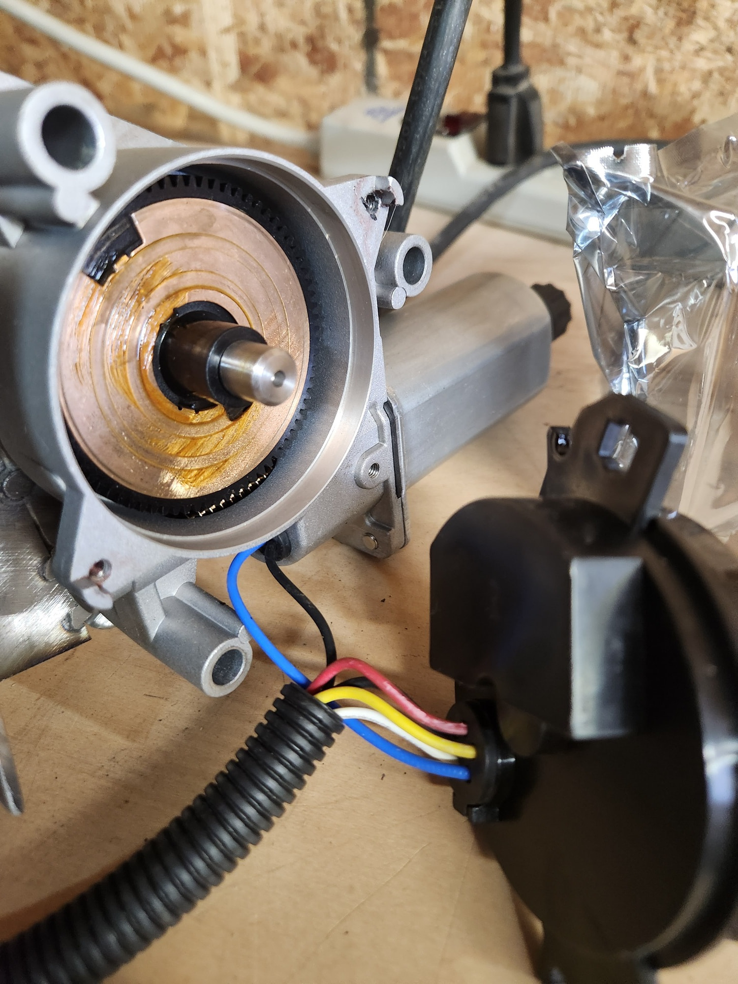
The copper disc with the two 180-degree opposed notches (one near the outer edge and the other near the center shaft) is the common contact of the “rotary switch” for the motor assembly. I noticed that this motor was sometimes hesitant. It appears that the sliding contact (not shown) that touches near the edge of the disc is actually over the edge of the disc sometimes. Build slop I guess. Regardless, the motor would stop before finishing the required 180 or rotation. I will be tweaking the sliding contact a little.
There is a SPDT relay (812H-1C) buried inside of this plastic housing. Right side of image with big shiny shunt between grounded pins 4 and 5. It appears that everything is diode protected/isolated from reverse voltages.
OK. PWM now works. A couple of careful changes and done.
Naively, one could think that adding the PWM circuit between the BATTERY and the the main power wire on the motor harness would do the trick. Although this may work under some weird conditions (I did not try it), it is the wrong thing to do.
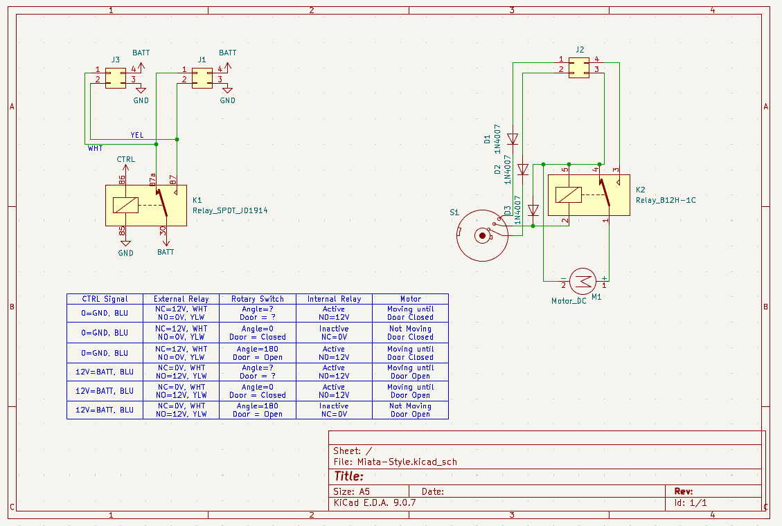
There are THREE items that need proper power: 1) external relay, 2) internal relay, and 3) motor. Only the motor must receive the PWM modified power. If the relays receive the modified power, they will not work as required and will essentially be turning on/off while trying to get the motor to move. For example, with the external relay modulating the power will actually make the internal relay think that you are trying to open/close the headlight doors hundreds of times a second (or whatever the cycle rate of the PWM is). Enough deep sparky stuff….
Changes:
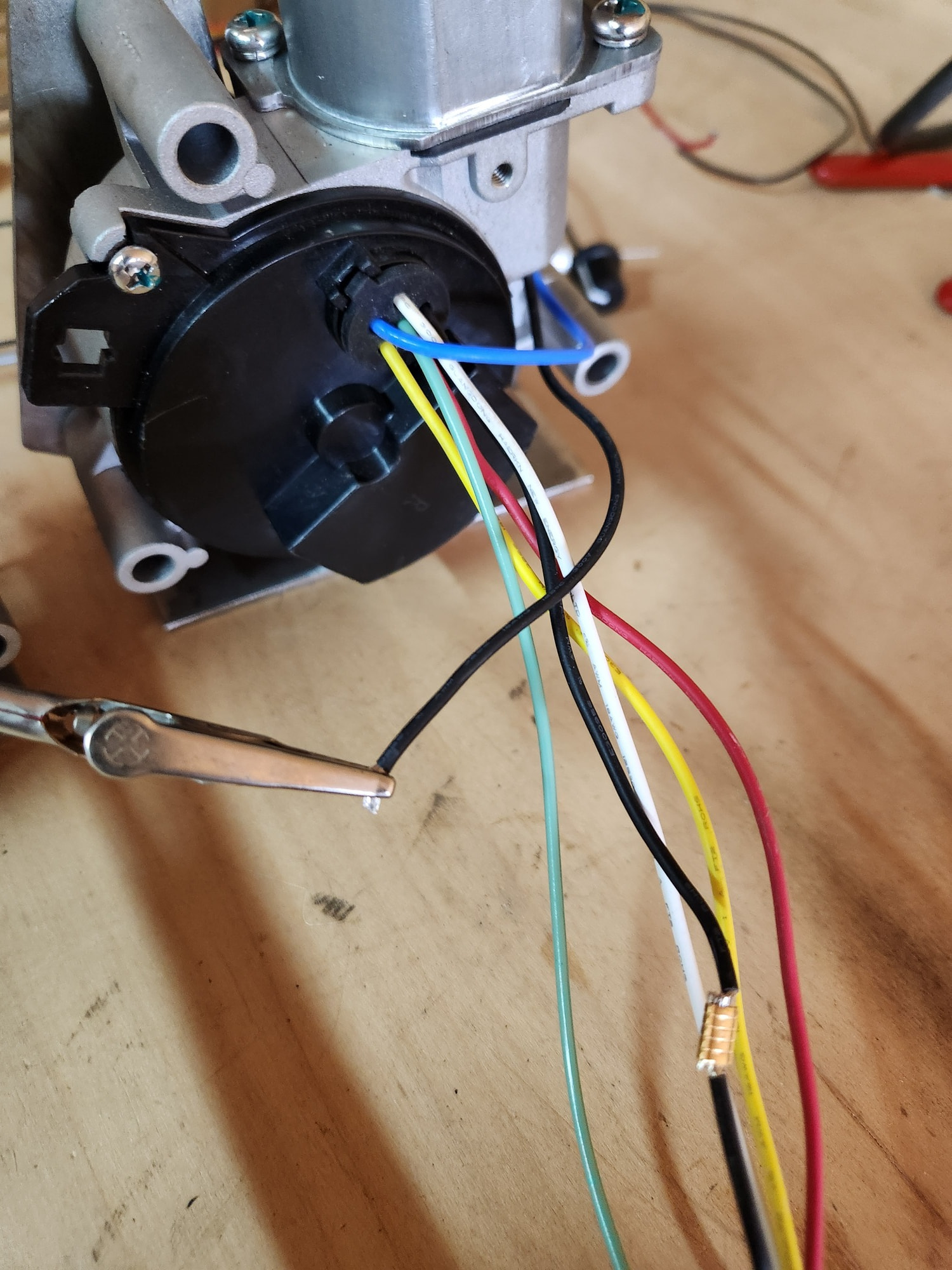
Tap into the green wire (red circle) and run it out through the rubber grommet. This wire will carry a 12V signal whenever the motor wants to move. This will be used to power the PWM circuit.
Isolate the motor ground from the other grounds. It is typical that PWM circuits are differential output and need an independent ground.
Cut the RED wires that go to the motors from the common 12V power. Connect the output from the PWM circuit to the RED wire on the motor-side of the harness.
12V BATTERY power should only go to the external relay.
You can also reverse the motor direction by swapping the +/- connections on the output of the PWM circuit.
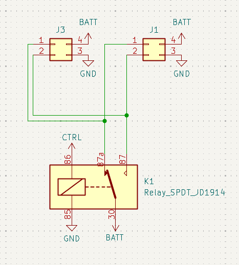
I’ll add a schematic later. But now back to grinding and welding for a while.
Thanks for posting this info. I just installed the economy conversion kit for 67-68 Cougar off of eBay. Several sellers seem to be selling these same kits now. I would like to slow down the speed and had read about a possible PWM solution for this but didn’t realize how much work it would entail. It does make sense that you wouldn’t want to pulse power to relays. Appreciate the info share on this and plan to revisit at some point.
Thanks for the feedback. This has taken a little work to figure out but I like a challenge. Adding the PWM modifications is actually pretty straight-forward (once you know how!)
@Martel How’s your project coming along? I had another thought on this. A single control to adjust speed would be ideal. Since both internal relays should fire at the same time, could a single adjustable PWM be integrated in to pulse both motors? Ideally you’d want to prevent voltage sharing from the PWM. Thoughts on this?
Damn good question. I’ve not thought that far. Been grinding and welding for the last few weeks.
At first blush, I’d say that one could power the PWM from one motor and then parallel the PWM output to both motors. HOWEVER, this brings up an issue with motor/switch phasing/sync where the “controlling motor” reaches its end position before the “controlled motor” and the “controlled headlight door” may not fully open or close.
Need to think on this. Thanks for the interesting feedback.
One way to do this is by adding additional relays and making a logical OR signal from the two signals from the motors. So either motor signal results in the PWM circuit getting power.