Looking for some guidance. 67 Std Cougar, non-tilt wheel. I found the dash harness was butchered up a bit after buying this car. Also, the TS indicator lights on the dash were on whenever the key was on. No blinking. But outside lights all work properly. The yellow wire was jumped across the TS connector. Bought a replacement harness and switch from WCCC and removed harness. Discovered the plate for the relays was missing from under the dash and the relays were floating in space not grounded. Bought plate from WCCC and new relays from Vic’s. Ended up replacing harness to the front of the car and a few other smaller ones. LED bulbs put in dash cluster. Everything lit up when bench tested.
On finishing install and testing the indicator lights are now off, but don’t blink either. All outside lights still work. Any ideas where to start? Thanks!
Having trouble with my sequencing tail lights in my ‘68. Car still retains the original motor operated sequencing unit from the factory…
The tail lights all work with brake lights and headlights working fine. The turning signals seem to work fine too however the outer lights on each side either don’t light up at all if the cars head lights are off or just stay on if the headlights are on…
I know there has probably been on a post on this very problem before (these old sequencing units seem to be troublesome part of the T birds/cougars ) but darned if can find it
Any help much appreciated, thanks
The outer tailights for both the left and right sides are powered via the sequential motor. The output of the sequential motor is then fed to the K10 relay where it is switched depending if the hazards are off/on. The output then feeds the K8/K9 relay which switches the output to the left or right side.
Coach Jack,
I am working on a 68 Cougar GTE with the replacement sequencing system in the back. When I got the car, I think that the blinkers were working, but did not test them or the flashers. This is what I know at this time. Did an engine and tranny rebuild, brake work, and had the voltage regulator off as well as the starter solenoid. Lots of detail work under the hood. All put back normal and all works fine as well as the charging system. New alternator. Fuse panel a bit dirty, but fuses are intact and good.
There are no emergency flashers or blinkers or dash light indicators. It is a tilt wheel car.
Brake lights, tail lights, and park lights work fine.
The turn signal switch looked original and had a return cam broken off. So I replaced it. Still no blinkers.
Pulled the instrument bezel to get to the 15 amp fuse for the blinker power on the orange wire with yellow tracer. Fuse fine and has power on the ignition side.
Reassembled the fuse holder and tested for power at the turn signal connector. Had power on the orange/yellow wire.
Re-plugged the turn signal switch connector and went to the turn signal switch. Has power on the blue wire on both the flasher switch and the turn signal switch.
Stopped at this point and wondering where to go from here.
Check for voltage on the output of the turn signal switch circuit 458 Orange-Black wire. If you have power here check the K7 relay as circuit 458 provides the input power. Next, test the output of the K7 relay circuit 459 Orange-Green. Circuit 459 then provides the input power to the sequencer.
Coach,
Will I need to use a “wire prick” to test the output on the turn signal switch or is there a terminal? the other two are terminals. Which one is the K7? Is it attached to the plate next to the fuse panel?
Coach Jack,
Gosh if you go under the dash and plug the connector onto the K7 relay……… Everything lights right off!!! I replaced the cable to the drivers side vent and installed a new master/PB assembly. Must have knocked it lose squirming under the dash installing these items!! I hate work under the dash. Even with the front seat out!! Thanks for your help, and all the useful information you have compiled. Need a carb rebuild?? I am your man!!!
Thanks for the video, do you have a video of the front as well ?
I tried them for the first time on my cougar this weekend, and whilst i’m amazed that they seem to work, they looked pretty slow (at least slower than in your video) and the front blinking is also very slow.
EDIT :
Is there also a reference of how the whole system should behave (for a 67) ? i.e. :
Turn left = front:flashes x time per 10 second ; rear:sequential repeating x time per 10 second ; dash : flashes
(on mine it seems the dash indicator shows 3 levels of intensity ?)
Hazards on = front:? ; rear:middle light flashes x times per 10 second ; dash:?
Brake = ?
I don’t, but could look at making one for you if it would help.
I would think one of the smarter ones here would be able to tell you about the speed of it.
Thanks for offering but i think i’ll do it the other way round, once i have the car with the engine running etc… i’ll do a video of mine and you guys can tell me if it’s the normal behaviour. Saves you the work of doing the video
Can you tell me which wires from the directional turn signal switch connect which wires in the wiring harness at the plug I have seen many pictures and I have taken many pictures of the plug and how the wires are arranged in the plug I pulled all the wires out of the plug when I rebuilt my steering column and the hazard lights are working but not the front lights and the directionals in the back are working but not the front directionals and now I wonder whether or not I have the wires in the plug connected to the wires in the harness correctly
The exterior lights on the 67 work fine with the exception of a dead socket on the driver side rear. Just the socket itself is faulty and needs attention as it was swapped with another that is working. Now, rather than the most outer light not being illuminated it is the center one. Simple. The interior dash indicators are another story. On either the right or left setting both indicators go off at the same time as if the ‘Emergency’s’ are activated. If some pressure is applied pushing in that switch to activate the ‘Emergency’s’ in then the dash indicators cut out. Am suspecting one of the under dash relays that control the turn signal or the Emergency’s and wires 49 and 50 that connect to these dash lamps or it most likely is the switch itself.
Starting with the k5 relay, verify circuit 441 which will have power when in right turn mode and flashers on, and no power when in left turn mode. Next verify circuit 49 has power in right turn and circuit 50 has power in left.
Next test the k6 relay, verify circuit 514 has power with the emergency flasher switch OFF and 514 has NO power when the emergency flasher switch is ON. Turn the emergency flasher switch OFF and put the turn signal stalk in right mode, now verify 49A has power (Note 49A is powered from the k5 relay’s 49 circuit).
Let me know what you find and then we can go from there.
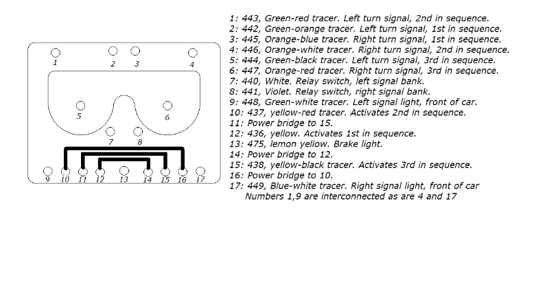
A few days ago I had posted a diagram of the relay that controls the sequential lights. The image consists of a facia with all the terminals, being 1-17 listed with their color code, color/s and function respectively. The primary objective behind the diagram is to A: simplify the unit itself into a more comprehensive illustration and/or to run diagnostic testing with either a continuity meter or a simple test light. For example, if you run a continuity test from terminal 13 through terminals 1-6 all should display a reading that the circuit is closed as 13 controls the brake lights. Energize terminal 8 along with the ground will cause the relay for the right hand turn signal to activate and open up the circuit for the brakes on that very bank. To test the circuits for the turn signal/emergency indicator lights the contact points when relays are activated being 7 Left or 8 Right are as follows.
Hi all! First time caller, longtime listener here. I have a 1967 standard Cougar that I’ve had for almost 9 years. Absolutely love this car.
I’m having this strange issue where when I put my left turn signal on, the high beams turn on and the high beam indicator bulb in the dash lights up as well. Similarly, when I put my emergency flashers on, the high beam bulb pulsates. My turn signals all work as expected, brake lights and emergency flashers too. Just the high beams is the abnormal part.
Here’s some details about my setup:
I have the solid state sequencer unit in the trunk and electric headlight motors.
Trying to chase this issue…I’ve replaced the turn signal switch, headlight switch, high beam switch, voltage regulator, checked my grounds and replaced the grounding cables, ensured I’m getting metal to metal contact. I’m kinda lost admittedly with electrical wiring.
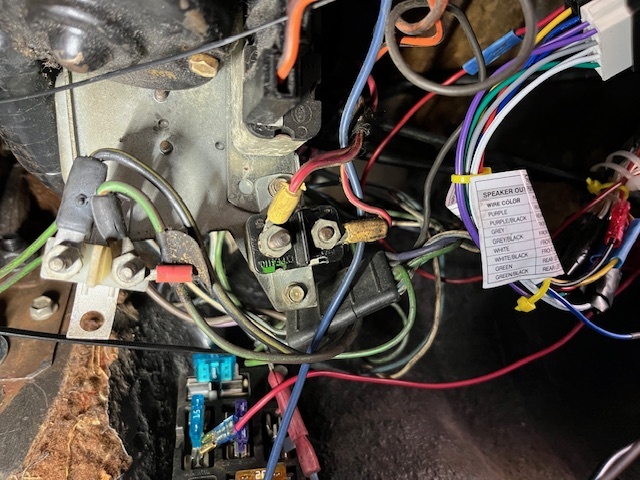
I know the solid state unit is supposed to replace the emergency relay and turn signal relay. I think those are still under my dash because I can here a clicking sound when I hit the emergency flashers. The previous owner butchered some things under the dash too I think when installing electric door locks. But here’s some pics of where the clicking is coming from. Not sure if I was supposed to remove these since I have the sequencer unit in the trunk but any help would be greatly appreciated.
I also have a recent related issue but is on the ‘68 Base. With the CU electronic sequencer installed in back and 1st time with incandescent bulbs, I had rear brakes, timed signals & hazard flashers in the 2 center bulbs all working, then after new plasma led bulbs no more dash signal indicators.
So then I upgraded the under dash flasher to the CU K5 solid state unit and that restored the dash turn signal indicators and also added on the click clack signal sound. Running lights, brakes and sequenced rear signals all work perfectly, but now when hazard switch is activated on column, the rear flashers no longer work.
EDIT: corrected sentence regarding order of installs.