Your parking lights are working correctly, they don’t stay on in the full on position. There is a relay that controls the dash lights. Over time the ciruit has gained enough additional series resistance to reduce the amount of current pulled through the relay. So it never fully opens. You can get anew solid state relay that will make it blink or open the one you have and very carefully bend the contacts to make it easier to actuate. (not recommended for amateurs…)
Thanks Bill. Huh, I would not have guessed that, the front parking/marker lights are not on with the headlights. Wonder why they did that?
Yeah, I read that about the relay, along with some other possibilities. Probably the relay though due to age. I’m adventurous. I’ll try anything once. Took my trunk lock apart the other night, and made it match my glove box key. Those stupid little springs kept getting away from me! ![]() BTW where would I see some pictures of your lime frost car. Love that color. That’s what mine is 390, 4speed, with ivy gold. Not XR7 though, and I bet yours has a vinyl top.
BTW where would I see some pictures of your lime frost car. Love that color. That’s what mine is 390, 4speed, with ivy gold. Not XR7 though, and I bet yours has a vinyl top.
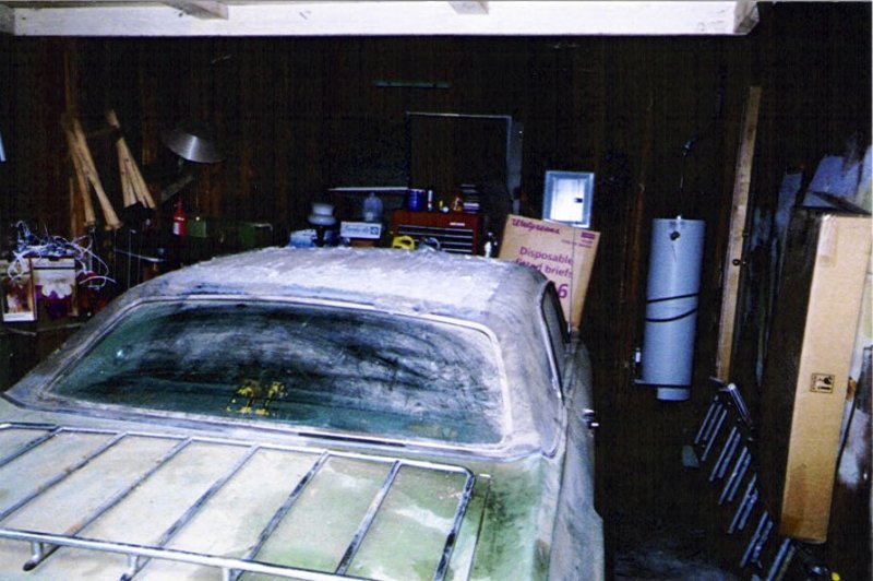
Before
After
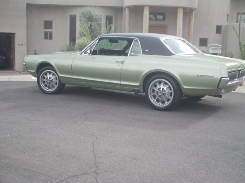
Nice! Like it better without the luggage rack ![]()
Sequential Taillights are a GO!
We finally got them working!
https://www.youtube.com/watch?v=i6NaH9-5gJc
1 Like
This is my first post. I have several questions concerning turn signals on my 68 base Cougar. First, a little background on what I have done to fix some of the electrical/light issues, what is and is not working in this area, and additional comments. I have replaced all non-working bulbs, headlight switch, brake light switch, and the fuse box. Headlights, taillights, and parking lights are working. Brake lights work only on the outside taillights. Hazard lights do not work and I have no lights (front or back) on or flashing when the turn signal indicator is placed in either right or left position. Both turn signal indicator dash lights come on in the appropriate locations with the turn signal lever but do not flash. I tested the orange/green wire going into the SQM and it has between 11V and 12V power with the turn signal lever in either left or right position. I have done no other testing in the trunk. The SQM is not running. I plan to replace all the mechanical turn signal items in the trunk with the solid state unit and this leads to my first question. Since I have power to the SQM via the orange/green wire does that mean the electronic unit should correct all my issues with turn signals and brake lights? If not what else should I test before purchasing and making the swap? I am not too concerned with the hazards at this time but this brings me to my next questions. I have 3 relays on the metal plate connected to the fuse box. Can someone validate my assumptions on these? I believe that one with 2 round posts is a circuit breaker. If so does the fact that I have power to the SQM via the orange /green wire validate that this circuit breaker is good? Is the larger oblong 3 pin connector device the turn signal relay which controls flashing of the dash turn signal indicators? Is the smaller oblong unit the emergency relay? I believe it is 2 prong. Thanks for allowing me to post and I apologize for all the questions.
Welcome abord DeNetMan.
In 1970, taillights flash from inner bulb to outer (I think was the same in 67) and if the inner bulb is not working and/or not well ground, there will be no flashing. Since you have the 4 inner bulbs not working with brakes on, I would replace them all 4 with brand new ones and I would abrade all 6 sockets & body contact surfaces to make absolutely sure that they all are well ground. That worked for me in similar circumstances, good luck.
Thanks CougarDan70. I have all new taillight bulbs and all 6 work with the taillights on so I would assume the ground is good for the sockets.
Are there significant differences in sequential turn signals for 67 and 69?
YES!!! the 67 (and 68s) are electro-mecahanical utilizing multiple relays whereas the 69 ( and later years) are solid state electronics.
Coach Jack
For an example of the relays in the 67… see the video above. I move to the inside after a few seconds so you can see the relays.
EDIT:
Or since this is on a new page… here you go.

My original post on this problem was back around Feb 20th. At that time I had no turn signals and my brake lights only worked on the outside taillights on my 68. I have since ordered and installed the electronic unit in the trunk. My turn signals are working fine now for both left and right. Now I do not have brake lights on any of the taillights. While testing I have managed to get brake lights temporarily when I unplug the white plastic plug to test the green-orange and orange-blue wires. When I plugged the white connector back in the brake lights no longer worked. However, this process does not always end with the same result. I have managed to get brake lights temporarily on all taillights, and once just the outside lights, and now back to no brake lights at all. I think I remember reading in the excellent troubleshooting documents that the brake switch on the 68 does not go through the turn signal switch. Am I correct in this? I am not always getting power through the green, green-orange, and orange-blue wires at the sequential flasher connecter in the trunk. I have checked my ground for the taillights and it seems to be working ok and taillights and turn signals are working fine. My ground is also connected to the new sequential box. This is a problem that I have to troubleshoot on my own which makes it difficult to know whether I always have enough pressure on the brake pedal. I would appreciate any help in narrowing this down.
Bill or Jack,
So I had the K7 relay open last night to see if I could figure out how it needed to be tweaked to get it to function. Is there more detail on this somewhere? Basically like a set of breaker points in there that are closed (if I recall right) when not energized. I cleaned them with very fine sandpaper while I had it open. I did watch it function with the cover off. Clicks once if the relay is “cold”, and then not again. If I activate two times in a row now it is what I call “warm” (not physically to touch, just terms I am using) and it don’t even click once that second time.
Something else curious though seems to be going on. If I activate left things sound different than when I activate the right. It seems like another relay up on relay board is engaging when I activate the right. I don’t have all 4 of my right bulbs working yet, is the only difference (missing one of the rear sockets, and need to change the harness on my Mustang repro right front light yet to match Cougar harness. So why the extra relay noise when activating to the right, but not the left?
Solid state trunk plug in works nice though. Left signals sequence nice and consistent in speed, and no clicking motor sound.
David
All the bulbs need to be in place and working for you to trouble shoot a flasher. Current flowing through the bimetallic strip causes it to heat up and then bend to break the contact. When it cools off, it will bend back, remaking the contact. To adjust it you will need to adjust the tension by slightly bending the fixed side of the points. I don’t recommend trying to bend the bimetallic strip. This is a very touchy adjustment, just a little bit of bend will do and the points must stay parallel to each other and in alignment.
It is very hard to adjust this relay with out a bench setup that uses an adjustable power supply. Basically, you need to bend over the upright post slightly to allow the solenoid to pull down the arm easier. I typically only bend the upright post about 1/64". It will tend to spring back. After bending it, you will need to reinstall and test it with various loads (headlights on, brakes on, etc). If you bend it too far, it will stick down. Too little, and it won’t operate over all the load and temperature ranges.
That is why I designed an electronic replacement. ![]()
I use a 10ft long 1"x2" board that sticks out the driver’s window to actuate the brake pedal. ![]() A tall mirror can also be used to monitor the brake lights.
A tall mirror can also be used to monitor the brake lights.
The brake light power is routed from the circuit breaker (next to the fuse block) on the 14ga green/red wire to the switch on the brake pedal. From the switch, it is routed on the 14ga green/white wire to the sequential controller in the trunk. As you noted, no brake power is routed through the turn signal switch on a 1967 or 1968 Cougar. First, verify that the circuit breaker is good.
Then verify that the brake switch is good by bypassing the switch with a short jumper wire. You can make one with two 1/4" quick disconnect male pins and 6" of 14 ga wire. Plug the male pins into the brake switch connector and check the lights in the trunk with and without the turn signals.
A common problem is that the aftermarket power disc brake switches use the wrong spring and require too much brake pedal pressure to actuate the switch. The solution is to use the Motorcraft power disc brake switch C9VY-13480-A (1967-68) or C9ZZ-13480-B (1969-70).
Make sure the two spacers and bushing are installed.
It is also very common for the brake switch connector to fail because the wires fatigue and break off due to the pedal movement. One solution is to obtain a new C8ZZ-13K408-AR brake switch extension harness (just released), cut off the male pin end, and splice the other end onto the original wires by soldering.
Working mechanical sequencer unit.
Working perfectly. I just cleaned up neglected bulb brass plates and bulb solder points.
What preventive maintenance overhaul do I need to do on the mechanical sequencer unit? One owner family before I rescued it. It’s working as it’s supposed to.
It needs TLC!
Any easy way to clean up bulb base? It was really hard to reinstall bulbs after removal.
IE push in to reinstall. I was concerned about bulb breaking lacerating hand. It wasn’t that hard on other cars growing up in the 70s 80s
Jack et al;
I recommended a 68 Cougar to a Ford club member and the turn signals quit. ![]() Emergency flashers work correctly when button pushed in. However with button out the system seems dead, left or right nothing. If I wiggle the flasher button the regular turn signals will come on. Took off the wheel and figured I could jump the flasher switch to verify that’s the problem. The shop diagram shows #44 blue bringing power into the switch, position 1. Coming out of position 2 the drawing doesn’t have a wire number so can’t figure out the color. I don’t want to just connect to anything and it’s probably on the bottom side of the switch. Can someone provide the wire number and/or color for position 2?
Emergency flashers work correctly when button pushed in. However with button out the system seems dead, left or right nothing. If I wiggle the flasher button the regular turn signals will come on. Took off the wheel and figured I could jump the flasher switch to verify that’s the problem. The shop diagram shows #44 blue bringing power into the switch, position 1. Coming out of position 2 the drawing doesn’t have a wire number so can’t figure out the color. I don’t want to just connect to anything and it’s probably on the bottom side of the switch. Can someone provide the wire number and/or color for position 2?
Thanks
Jim
The turn signal switch contains 2 power input circuits, circuit J10 (Green-Red) powers the emergency flashers and circuit J8 (Orange-Yellow) powers the turn signals. Rather than trying to jumper a wire in the switch, you should make sure that the input power circuit for the turn signals is providing power.
Circuit J8 starts from the Acc post of the ignition switch then passes thru an inline 15A fuse before connecting into the vehicle turn signal harness. Put you multimeter in DC volts, put the ignition switch into the ACC or Run position and measure the voltage at J8 at the turn signal harness. If you do not have power here, then back up and check the fuse. Once you have power at J8 and the signals still do not work, then carefully examine the turn signal switch for any signs of burn or scorch marks. If there are any signs of damage, it would be best to replace the switch.
Coach Jack