I am a brand new member of the Classic Cougar Community. I spent time this morning looking on the forum for help to identify 4 wires that have been cut in the under dash wiring harness on my '70 Cougar Eliminator 351C auto with factory sunroof. But I still did not find out where those wires go. So I have several questions:
The first wire is black with a blue stripe. It comes out of the main harness about half way between the steering column and the left side of the interior. On a '69 Cougar, that wire appears to go to the left hand side under dash courtesy light, but I believe it is an all black wire that goes to that courtesy light on my '70 car.
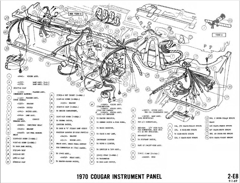
The second wire is light blue with a red stripe. It is cut very soon after it leaves the #17 position on the natural colored plastic plug that plugs into the back of the instrument cluster. When I looked at the '69 Cougar, the light blue with a red stripe wire leaves the #8 position on the natural colored plastic plug that plugs into the back of the instrument cluster and then enters the wiring loom. I did find on the '69 Cougar, that the light blue with red stripe goes to the headlight switch, and another branch of this same color of wire goes off toward the right side of the '69.
The third and fourth wires are light blue with a red stripe and yellow with a black stripe. Both are cut about 5 inches after they leave a 2 pin connector that exits from the main wiring harness about halfway between the steering column and the right side of the car. Yes, the light blue with a red stripe wire here matches the color of the second wire mentioned above.
All other wires appear to be intact.
New wiring questions:
Is the wiring harness for a 1970 Cougar Eliminator with standard interior the same as for the same year XR-7? The reason I ask is that I would like to hook up the wiring connectors that come from the 4 switches (map, courtesy, panel, accessory, and that fit into the middle of the dash) to the main wiring harness.
I also want to add the B-pillar courtesy lights (for deluxe interior) to my car. Where do they connect to the main wiring harness?
and 7. I do have the Jim Osborn '70 Cougar Wiring and Vacuum Diagram booklet, but I am still confused. Part of the confusion seems to be that there is no single complete wiring diagram, but only specific circuits for specific functions. Also these wiring diagrams refer to numbered assemblies, e.g.14301, but there is no table of those assemblies to tell what they are or where the wiring goes from those numbered assemblies. Does any supplier have a large complete wiring diagram that is color coded for the wires so circuits can be followed from beginning to end? It seems like there also should be a list that decodes the numbered assemblies on the wiring diagrams in the Jim Osborn booklet/Ford-Mercury Electrical Manual.
I would greatly appreciate your help and advice! Thank you!
First off, Welcome aboard! I know you are busy sorting out wiring issues right now, but I hope you will share some pictures and details about your Eliminator in the future.
Getting late for me to dig into the diagrams, but I’ll try to take a look tomorrow unless Midlife beats me to it
If we can’t get things sorted, or get a straight answer to your wiring questions, I can do some digging under my dash and try to get some pics to help you out.
Eliminator uses the XR-7 wiring harness, except for the section that goes to the four switches you asked about. If you have the switches and thier harness you should be able to add it in though.
Have you checked the West Coast Classic Cougar video for adding the courtesy lights to the '67/'68?
One of the comments from WCCC says:
If you have an XR7, or if your car was ordered with the courtesy light option, then the wiring will be there. Otherwise, all 69-70’s have it on the LH side (built in to the taillight wiring) but on the RH side you need a separate piece of wiring. We can usually dig up a good used one if needed, give us a call at (503) 463-1130. Also keep in mind that 69-70 cars use a different light assembly than the ones shown in this video. We have them new on our website.
Thanks very much for your replies Midlife and Mike B.!!
In response to Midlife:
1, If the black with blue stripe wire is a “switched courtesy lamp wire,” then I just need to figure out where that switch is located. I will check to see if it might be the “Courtesy” switch in the 4 switch panel in the middle of the dash ("10B923 wiring assy.) as shown in the diagram above.
2. Does “Dash lamp wire” include instrument cluster or what else?
3. Yes, wires 3 and 4 are going to the radio; figured that out looking back at diagram 2-E8 above and 2-E31 (radio stereo tape).
In response to Mike B.:
At some point I will post photos, but my primary goal is to finish this Eliminator in time to take it to one of the Cougar 50th Anniversary Celebrations. What other sites are there for Cougar 50th Anniversary Celebrations besides the one at the 2017 Carlisle Ford Nationals? I would prefer to go to one closer to Texas.
Very helpful to know that the “Eliminator uses the XR-7 wiring harness!” I do have the switches, switch panel and the wiring harness that goes to the switches.
I have not looked at the WCCC video about adding the C-pillar courtesy lights, b/c I did not know about it–thanks for telling me!
The Osborn wiring diagram is the same as the WCCC electrical schematic available for free download (which I have downloaded; my thanks to WCCC!!).
Some of the assembly numbers are on the 2-E8 instrument panel diagram, but not all. So is there no place to find a list that identifies the numbered wiring assemblies?
Again I want to say a big THANK YOU!!! for the help provided.
The closest 50th Anniversary show to Texas will be the one in Tulsa, Oklahoma on April 22nd. https://www.midamericaclassiccougars.com/2017-nationals
I’m also trying to ready a '70 Eliminator for that show. I’m making progress, but there’s a long way to go. It’s going to be tight. But I’ll be there regardless, and I’d love to see your car.
As far as the wiring, there’s not much I can add without the car or manuals in front of me, but the blue with red stripe is definitely for illumination of dash accessories (radio, gauges, ventilation control panel, ashtray and clock, off the top of my head.) Its a dimmable circuit controlled via the headlamp switch.
Black with blue may be the power feed to the door jam switches that control the interior courtesy lights, but my memory is fuzzy on that one.
Anyhow, good luck, and please keep us posted on your progress.
I am still stumped and very frustrated primarily because I cannot figure out where the black with blue stripe wire needs to go and the same issue for the light blue with red stripe wire!!
A. I looked to see if there was a light blue with red stripe wire attached to the fuse panel. I found 2 such wires attached to the fuse panel–no need for another one there. Also, there is a light blue with red stripe wire attached to the headlight switch connector as it should be (to dim dash lamps). Does the light blue with red stripe wire (which connects to the instrument cluster plug) serve as the power source wire for the lights in the instrument cluster? If that is correct, then can anyone tell me where the other end of this light blue with red stripe wire should be connected??
Light blue/red stripe power comes from the headlight switch. Goes to fuse box, and then out to all of the dash lamps and associated lamps. There should be 2 blue/red wires at the fuse box: one innie, and one outie.
Thank you for your quick response, Midlife! Yes, the blue with a red stripe wire going into the fuse box from the headlight switch (# 19) and back out (as # 19A on the schematic for “1970 Cougar Interior Lights”) makes sense. The # 19A wire goes to what appears to be a 'splice" on that same wiring diagram. From that splice, # 19C goes to the 14489 plug that plugs into the back of the instrument panel. # 19D goes to a red 3 female hole plug which I found earlier, and # 19B goes to the radio plug for the radio light. All # 19 wires are blue with a red stripe.
So now I am thinking that I need to follow the # 19A wire out of the fuse box to find the splice to the other #19 wires. When I find the one that has been cut, that should be the one to connect # 19C (my cut blue with a red stripe wire), right? Sounds “easy” but this means possibly unwrapping much of the main under dash wiring harness as best I can tell.
I am soldering wires together and using heat shrink tubing to protect the soldered joints; is there any better way to make wiring repairs?
OK, it is now 10:00 a.m. here and I’m back from chasing the blue wire with a red stripe. After unwrapping the main wiring harness over to the location where the wires leave the main harness to go to the plug for the instrument cluster, then I continued to unwrap all the way up to that plug for the instrument cluster: you probably guessed it: the blue wire with a red stripe had been cut (and the exposed copper wire covered with tape) and just stuck back in the harness (but not attached) to the plug for the instrument cluster. So now I have 2 soldered repairs within about 3 inches on the # 19C blue wire with a red stripe, but at least it should be functional. Party time!!
But wait!..I found 3 new issues:
At position #12 on the plug for the instrument cluster there are 2 wires:
a. a violet colored wire that is intact
b. a black wire that is supposed to go to ground, but it is cut. I have not been able to find out if it should connect to another black wire in the main harness or go by itself to a ground on the dash. Any ideas?
The green wire with a red stripe that the wiring diagram shows hooked into the instrument cluster plug at #8 position came loose and it won’t stay locked in the instrument cluster plug at #8 position. Can I use a very small amount of clear silicone sealer at the #8 position to keep that wire from coming loose?
Position #3 on the plug for the instrument cluster has NO WIRE AT ALL. Is that the way it came from the factory??
I have also started tracing the # 53 through # 53F black wire with a blue stripe mentioned above. That color of wire goes to lots of things, e.g. clock on pass. side dash, foor jamb switch for courtesy lights on both sides of the instrument panel, left and right hand door courtesy lamps, left and right hand “C” pillar lamps. Going back out to see if any of the black with a blue stripe wires to these end points might be cut. I just know that I have one black wire with a blue stripe cut under the dash.
I have seen factory splices fail to a certain extent, but not to the point that no voltage passes.
Do you have continuity between all blue/red lamps with each other, but not to the fuse box? If so, then the break is on the fuse box side of the OEM splice. If any lamp has continuity with the fuse box, then the break is on the other side of the splice. Sometimes, Ford had wires going into the splice with the input side as well…sigh
Solder and heat shrink is good; be sure to wash the solder joint with alcohol to eliminate any flux; the flux can corrode the joint over time.
There’s a big ongoing debate in the electrical community of solder vice quality butt-splicing; there are pro’s and con’s for each. I use butt-splicing primarily because it is quicker to perform. I go through about 2 boxes of 1000 butt splices a year; doing all of those with solder would slow me down by about 10 -15 minutes per splice.
Thanks for the input on soldering wires–I did not know about rinsing with alcohol to remove the flux!
My main two questions at this time are the following:
(#3 above) Position #3 on the plug for the instrument cluster has NO WIRE AT ALL. Is that the way it came from the factory??
An even greater question in my mind involves the fuse box under the dash:
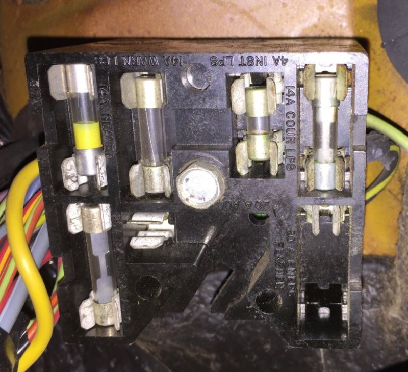
The fuse panel for the Mustang and Cougar is shown in the WCCC free download for the 1970 Cougar wiring and vacuum diagram and on Page 36-03-03 of the 1970 Car Shop Manual volume 3 electrical. That fuse panel diagram shows the number 7 circuit (20 amp.) EMERGENCY WARNING, HORN (MUSTANG ONLY) with a fuse in place and both ends to hold the fuse. On my '70 Cougar Eliminator, there is no fuse and only one end to hold the fuse. There is NO WIRE leading to the one end where the other fuse holder end should be for this EMERGENCY WARNING circuit. It looks like it was made that way from the factory; is this common on '70 Cougar Eliminators???
Please address both of these questions. Thank you again for all of the help!!
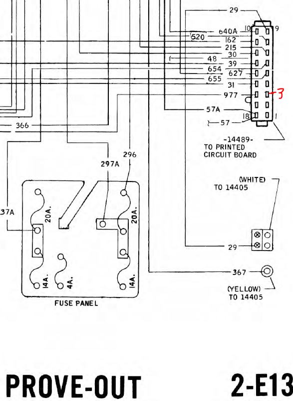
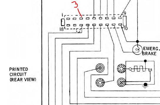
Judging from the Prove Out diagram (pg 2-E13) and the Guages diagram (2-E14) it looks like pins 2,3,4, 17 are all “empty”.
This is the connector you are looking at, right? I don’t think I can access that without some disassembly. Maybe someone else has thier dash apart and can comment or post a pic.
351 ELIMINATOR, AUTO AND SUNROOF sounds very familiar Put up some pics of the car if you can.
Ive got the loom out of mine on the bench atm, so if there is something you are still not sure about or need a photo just let me know.
First, the photo of the fuse panel from your '70 Cougar Eliminator is a wonderful help, Mike_B_SVT! That is exactly how my fuse panel looks at the EMERGENCY FLASHER fuse location (no fuse and no wire attached to the back of the fuse panel where the other end of the fuse holder is also missing).
Yes, a picture is worth a thousand words!
Second, regarding the connector that plugs into the back of the instrument cluster (yes, the one shown in the 2 diagrams you included), I have wires at all of the other 17 positions in this plug–only the number 3 position has NO wire at all. Thanks to Mike_B_SVT.
Third, Midlife’s response is very reassuring: “Yup, all normal from what I’ve seen on Cougars of that year.”
Fourth, to Comp Elimn8r, sounds like your car is very close to mine except for the comp green color. I will get to pictures eventually, but right now it looks very messy!! I do have the following questions about 2 wires:
a. There is a black (no stripe) wire coming out of position #12 (where there is also a violet colored wire) on the 18 position plug that plugs into the back of the instrument cluster. The wiring diagram shows this black wire going to ground. This black wire was cut about 12 inches away from the plug. I cannot find the other end of any black wire to connect it to, so I plan to just put an end on it to allow this wire to be held to the dash with a screw. If you can see this wire, then please let me know where it terminates.
b. I still have a black with blue stripe wire that was cut in the main wiring harness about 8 inches to the left of the steering column (left hand drive for USA). I cannot find the other end of any same color wire to connect it to, so where does that wire terminate on your car?
a. There is a black (no stripe) wire coming out of position #12 (where there is also a violet colored wire) on the 18 position plug that plugs into the back of the instrument cluster. The wiring diagram shows this black wire going to ground. This black wire was cut about 12 inches away from the plug. I cannot find the other end of any black wire to connect it to, so I plan to just put an end on it to allow this wire to be held to the dash with a screw. If you can see this wire, then please let me know where it terminates.
No no no! It does not go to ground, but is called a “blind circuit”. It’s purpose is to provide strength to the violet resistor wire that has a single strand. That resistor wire cannot be crimped by itself with normal pins expecting 16-18 AWG wires, so Ford added a short section of black wire to provide a proper crimp. The other end of the black wire is supposed to be buried in the harness bundle under tape where it cannot contact other lines or be shorted out. DO NOT GROUND THIS WIRE! It will cause the resistor wire to carry more current that it is capable of and cause the insulation to burn and possibly start a fire under the dash.