I have been rebuilding these professionally for several years. It took a long time to learn what needs to be done and then develop the technique for making them better than new. I am not ready to stop rebuilding these yet but I also don’t want the knowledge of how it is done to disappear if for some reason I was not able to go forward.
A long time Cougar guy was asking about how to do this on Facebook. I started messaging back and forth and it became apparent that this should be shared with more than one person. Facebook posts vanish very quickly so posting it here is a better place to share the information.
In typical Facebook fashion well meaning people began to provide their guesses about how this might be done. So the misinformation began to roll. Some one familiar with GM senders suggested that his sender should read zero ohms when empty, the exact opposite of Ford. Another poster knew the gauges ran on 5 volts but was unaware that it could not be measured with typical meters. Eventually someone would suggest bending the float arm, thinking this worked like a toilet tank valve. Eventually acting on these suggestions will result in ruining a very hard to find core. So my responses began here:
First off you wont be able to measure the output of the instrument voltage regulator with that meter. It puts out pulses of 12 volts that average to 5 volts over time. Only a few digital meters have the capability to measure and average voltage in this way. Think of a very primitive but effective version of pulse width modulation.
To save you time I can rebuild calibrate and test your sender. It will run $125 including a new thermistor that can handle the 15 volts common with modern voltage regulators. It also includes a new brass float, filter and seal ring plus return postage by Priority Mail. Turn around is less than a week.
I support DIY with this caution. Rebuildable cores are incredibly scarce. It is very easy to ruin one. You need to be proficient in soldering as that is what you are going to be doing a lot of.
The right way to diagnose gauge problems is with a tester. You just unplug the wire to the sender and you can verify that the gauges are getting power, and reading accurately at high low and mid positions. Inaccurate gauges can be recalibrated by Rocketman for just $15… But let’s talk about what you can do without a tester.
How far off is the gauge? A good way to start is to connect the sender, outside the gas tank, to the harness using a clip or test lead to to ground the sender to the mounting flange of the tank. Turn the key to the accessory position. If you have a Pertronix 1 or points, it is critical that you not put the key in the Run position. Now raise the float arm to the upper stop and hold it. Give the gauge at least 30 seconds to respond. The gauge should read full.
What we are doing is trying to determine if the gauge is off or if the sender is off or something else. If you get no reading then unplug the harness and use the clip lead to briefly ground the fuel level in the harness. The gauge should move very quickly to peg above full. Do not leave it hooked up for more than the time it takes to see this. If the gauge does not move you have a problem with the gauge or the instrument voltage regulator on the back of the cluster. Note: a bad IVR will effect fuel temp and oil pressure. If the other gauges are working correctly then the problem is the gauge. If the gauge reads low, and the other gauges are all working it is about a 70% chance that the sender is the problem.
When I get a sender in the first thing I do is to test it in this test bed. This is the Ford circuit. I am testing under load. Things can measure well on a meter with no load, and then fail here.
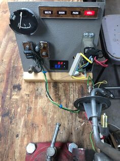
If it’s close to being right then we know that there is a good chance the gauge is the source of the problem. Typically I would ask the owner how what I am seeing compared to what they saw in the car.
Once we have settled on the sender being the issue the first step is to disassemble it and clean everything. That can start with a day in the parts washer. Then possibly Evaporust taking care not to allow the resistor housing to be immersed. Finally into the blast cabinet. The sender is grounded to the tank through the flange. It needs to be free if any sort of residual layer of any kind. Do not use any kind of oxide material. It’s conductive and will ruin the internal wire wound resistor. Only glass and silica. I also blast out the inside of the pickup tube.
When opening up the resistor housing use great care not to bend the tabs over center. They will break and you need them. The inside surface of the housing has to be cleaned. A piece of blue tape over the coil, but revealing the rivet where the coil is terminated, will provide protection.
The area where the axle passes through the inside of the housing, is particularly critical. This is the main ground connection between the sweep arm and the sender
I unsolder the brass thermistor housing from the clip. Then I open the crimps and remove the plastic insulating plug. Desolder the remains of the old thermistor. Remove the internal screen and clean it carefully with solvent. It controls how fast gas can enter the thermistor housing. Polish the housing and the connections on the insulator.
The real process begins now. You have to zero out every electrical connection meaning 0 ohms or as close as possible. 1 ohm is 10% of 10 ohms. We need to be able to see 1/10th of an ohm. Most meters are not accurate at low resistance measurements. I use a Fluke bench top that is ridiculously accurate.
Start inside the resistor housing. If you look closely you can see that the end of the resistor wire goes under the rivet. Use the edge of a razor blade to remove the layer of oxide on the wire to create a clean surface that you can solder to. You now need to build a solder bridge from the rivet to the wire. This is not easy. If you are not sure about your soldering skills do not attempt this. There is a plastic insulator that will melt if overheated. Nichrome wire doesn’t solder easily. I use a light flux and silver solder.
Next wet sand the wire wound resistor. De-Oxit 5 is best but carb cleaner will work. Use 600 grit emery paper only with the grain of the winding. Never go side to side. The coil can shift and ruin your sender. NEVER use a pencil eraser. The rubber nibs get under the coil windings and lift it where the sweep arm can get hooked under the wire.
The sweep arm has a small contact pad on the end. It needs to be reshaped with a jewelers file. In particular the leading edge and corners need to be slightly rounded. It becomes sharp and can hook a coil on the resistor and ruin your sender. Use a pick or thin screw driver to hold the sweep arm clear of the coil as you close the resistor housing. Use a large alligator clip, like you would see on a battery charger, to hold the case closed. Do not bend the tabs yet.
We are getting to the easy part! Now solder the connection at the top of the resistor housing and both connections at the mounting flange. Note: if there is any wobble from the studs you can tighten that up by carefully peening them from the back side of the flange. An old punch with the sharp tip ground off works well. Don’t overheat the plastic insulators.
The most delicate part is soldering in the new thermistor. This is a heat sensitive device. Only one person I provided just the component to was able to do this and he was a EE and swore he would not do that again. I use a heat sink and I have it down.
Anyway the thermistor is threaded through a tiny hole in the brass housing, the crimps at the base are closed and the wire is soldered to the brass housing. Then the housing is soldered to the bracket.
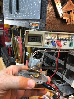
At this point connect to your meter on the lowest ohm setting. On a meter with a 200 ohm setting it can easily be off by more than 2 ohms (1%). This is a problem because we need to be able to see 1/10 of an ohm. There are some pretty good auto ranging meters on the market that are fairly accurate and affordable.
The first step is to open the resistor housing and verify that you have less than 1/2 ohm from the connection point at the out side of the flange all the way to the first winding on the coil, right at but not touching the solder connection. Anything higher means go back and find the high resistance connection. If you’re in spec, examine the sweep arm to be sure it is straight and plumb. It must track down the center of the coil. I have a cutaway I use to verify this but it can be eyeballed. Then note how the contact patch meets the coil. It must never dig into the coil. There is a sweet spot in the middle where you want it to touch.
Close the case and connect the meter to the fuel level terminal. Ideally you will read just under 10 ohms 9.5 is good. Below 9 is too low.
If you have hit the target you are ready to close the tabs. They don’t need to be bent any farther than what it takes to close the case.
If it’s not on target adjustment is done by bending the sweep arm. It is best to secure it with one set of pliers and then use a second set to very very slightly bend the arm. We are talking less than 1 degree. Close the case and check your work. Repeat as needed. This step can take the longest. Be patient and gentle. Opening and closing the housing always be careful not to hook or bend the sweep arm.
I seal the electrical connections on the inside of the flange. Seal All or Red Coat works great. I also use silicone Teflon spray to protect the entire surface
ACP has the best brass float WCCC sells them, NPD and WCCC have the best filters and seal rings.
One last thing. Do not paint the sender. Paint is an insulator and it will make your sender either not work or way off.