Can someone give me a quick class on the cooling system in my '67?
1). Does the water flow into the radiator from the bottom and out the top?
2).When checking temps on the radiator hoses, the temp is similar on both hoses when checked near the radiator connections.
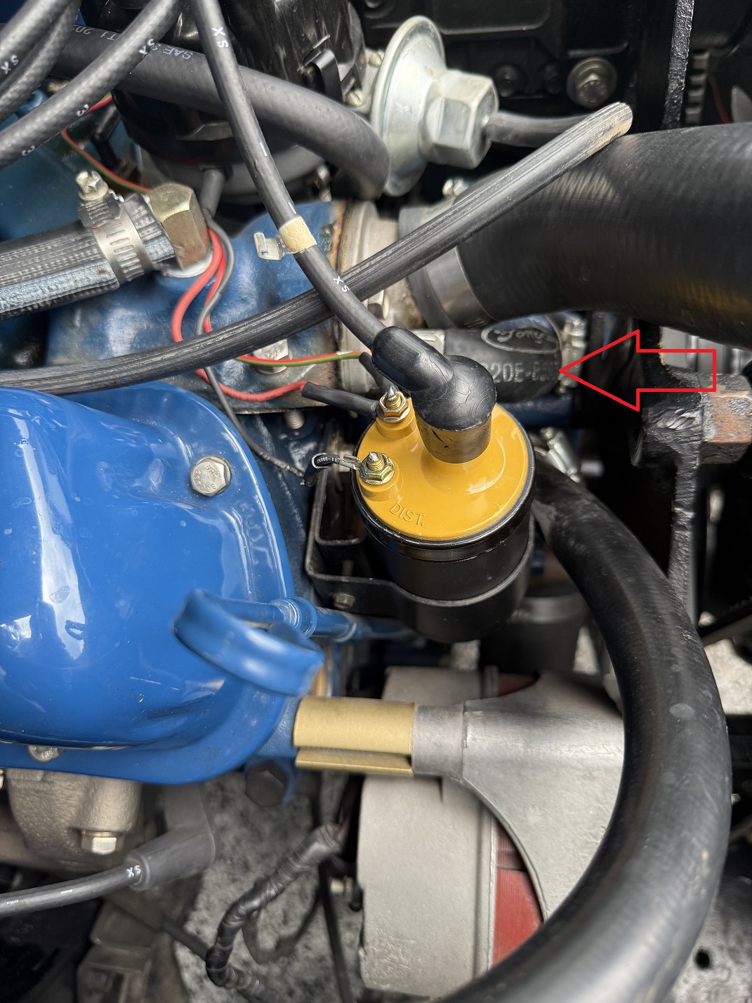
3).What is the purpose of this bypass? (see arrow)
4).How can I easily test to see if my water pump is providing the proper flow?
Coolant flows out of the engine through the thermostat and into the top radiator hose. Then down through the radiator and out the bottom hose into the water pump. The water pump pumps coolant into the engine block.
The small bypass hose allows some coolant to recirculate through the engine during warm up before the thermostat opens.
To check flow, leave the radiator cap off until the thermostat opens. You should see coolant flowing through the radiator at that point.
With the thermostat open, top hose should measure 25-30 degrees warmer than bottom hose.
Hi, the water flows into the radiator from the upper hose. The lower hose returns to the water pump and then moves thru the motor. The small bypass hose helps to keep coolant flowing in the motor even before the thermostat opens, then once open the flow in the bypass slows down.
to test the water pump flow, you can have the cap off for a bit and after the thermostat opens, you should see good steady flow coming in from the upper hose connection.
For the heater hoses, the one on top of the intake should go to the left side of the water valve. then the water valve has a small hose rt side going vertically down to the left connection on the heater core. the right side of the heater core should have the hose routed to the water pump connection.
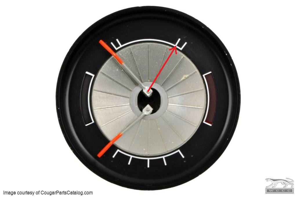
Thanks. My mind had the water flowing the wrong direction. I’ll try watching for flow with the radiator cap off. I’m perplexed because while it doesn’t overheat, it runs hot. I don’t like it so high up on the guage…
Shurley the current batch of reproduction senders can be way off.
Does the fuel gauge also read higher than expected? If so that points to the Instrument Voltage Regulator. If not then the issue will either be
It is running that hot. Use a non contact infrared thermometer to check the temperature at the temp sending unit location. If you get something around 192 degrees then the car is not running hot. I would expect to see 210 or better to get the gauge that high.
2.Is the sender that far off. At 192 degrees the resistance across the sender should be around 23 ohms. If the sender is lower than that (like 12 ohms) it is the problem
If the sender checks out the gauge is out of calibration. Rocketman can recalibrate it for just $15.
I don’t know how long you have been looking at your gauge but it is summertime. If this is your first summer with the gauge it may read a needle width or more above “normal”. Especially after a heat soak. Ya take it to the store, then, on the drive home its higher than normal untill highway use to even it all out. Could be 10 miles. If you live 3miles form the store, it may not have time to even out before you get home. After a few years of looking at that gauge and it seems off, then that’s different. My point is that it doesn’t seem like there is a problem. Look when its cold and see if it needs any fluid. Check the condition of the antifreeze or mixture. If the needle gets in the red or pegged shut it off in a safe place.
Agree there a lot of variables on temp drop across radiator. But assuming the thermostat is open, fan and water pump are turning, and radiator is not covered, you need to see a temp drop from top to bottom radiator hose. If they are equal, the cooling system is not cooling at all.
Speaking from experience, a stuck thermostat and a fouled cooling system are common problems, regardless how pristine the engine compartment appears. Make sure you’ve got a working thermostat and flush the system prior to filling with new coolant.
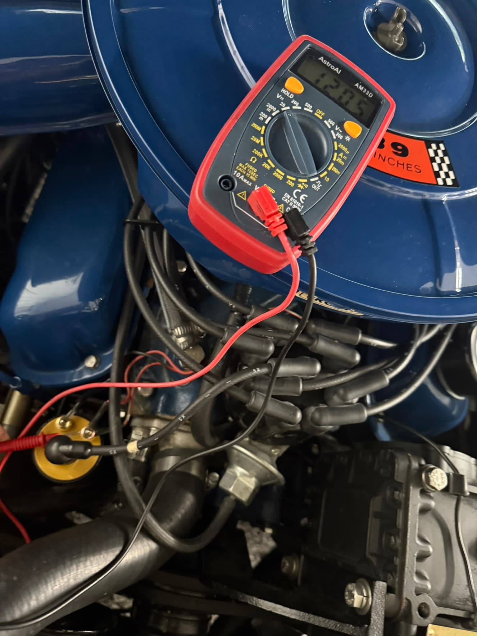
“Looks like” is a very good answer. Until current is flowing through a circuit what you will measure is potential voltage. When current begins to flow then you will see the voltage drop in the circuit across, in this case, the resistor wire in the ignition circuit under the dash. IT IS possible that at some point the resistor wire was by passed but that seems unlikely as it looks like the factory harness is still unaltered, and more importantly it appears that you are using the stock yellow top coil that is designed for reduced voltage and will overheat with a full 12 volts. If you measure voltage at this point with the engine running we can see what the voltage really is.
Now you have me confused. You stated: “You should know that the Pertronix Ignitor you are running is installed incorrectly. They hooked power up to the coil where it will only 9 volts maximum and it needs 12 volts.” Now you say the coil will overheat with 12 volts.
What’s the correct answer???
Maybe I’m wrong, but it sounds like he’s saying that you want the constant 12v. and that you also need to buy an upgraded coil to have everything right.
The coil should be connected to the same power wire that it has always been connected to. It will supply 9 volts or less and the coil will be happy. The Ignitor needs 12 volts. The connection to the coil POSITIVE is incorrect. It needs a 12 volt supply. So you disconnect it from the coil and power it with 12 volts. The 12 volt power doesn’t go to the coil.
The Ignitor is an electronic switch. It connects and disconnects the ground side of the coil. It senses magnets that are embedded into a plastic ring that rotates inside the distributor. When the ground is lifted the magnetic field inside the coil collapses and the new path to ground is through the distributor and the plug wires to the spark plugs to the block.
The Ignitor needs 12 volts to operate properly. Much of the confusion comes from the fact that it has two wires, red and black and people do not understand the function of the two wires. Red is power and it has to have power when the engine is cranking and running. The black wire is not the electrical ground for the Ignitor. It’s the switched lead. The electrical ground for the Ignitor is the metal base plate where it is screwed down inside the distributor. So you add a new device, the Ignitor, and you need to provide a new power source.
There really aren’t any dumb questions. If it’s still not clear please ask. Electronics cannot be understood by looking at them.
Thanks for the explanation and connection details. This is exactly what I need to do to correct PO mechanic’s incorrect installation. Your relay will go in this weekend.
Given that the car was driven for a year with that incorrect setup, once everything is corrected, is there any way to test the integrity of the Pertronix and that it’s not been damaged?