Thx Keith. Unfortunately I have a 1970 without a tach or a red-green wire.
I’ll figure it out, with the Pertronix power relay or Rocketmans.
Thx Keith. Unfortunately I have a 1970 without a tach or a red-green wire.
I’ll figure it out, with the Pertronix power relay or Rocketmans.
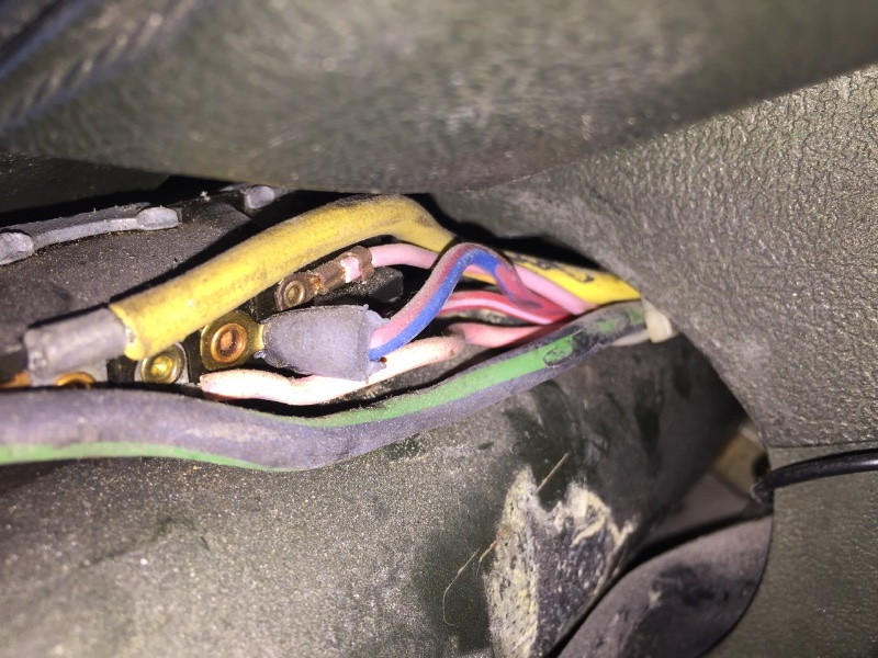
wbferran, I do see a pink wire. Stick a straight pin into it and use a test light to see if it is hot during crank and run.
Some confusion about which Ignitor works with which coil.
The Ignitor is a switch. Switches are rated according to how much power they can handle. Power (Watts) is current times voltage. The amount of current is determined by the resistance of the coil. Current is calculated by dividing voltage by total resistance in the circuit. So you have a 1.5 ohm resistance wire in series with the coil. If you run a 1.5 ohm coil (Flame Thrower 1) the total resistance is 1.5 ohms plus 1.5 ohms for a total of three ohms. So engine running, alternator putting out 14.4 volts you get 14.4 divided by 3 for 4.8 amps of current. This is what the Ignitor 1 is rated for.
The Ignitor I is for use with the stock coil or Flame Thrower II.
The Ignitor II can handle more power. It is compatible with the stock coil. It is also rated for use with the Flame Thrower II .6 ohm coil. Using the Flame Thrower II you get .6 ohms from the coil plus the 1.5 ohms from the resistance wire for a total of 2.1 ohms. So engine running, alternator putting out 14.4 volts you get 14.4 divided by 2.1 ohms you get 6.85 amps of current. That is just under the 8 amp rating of the key switch. However, if you have an XR-7 with a stock tach that much current will cause the tach to possibly read funny and or fail. You would be well served to get a Rocketman three-wire tach that won’t be effected.
The Ignitor III is not compatible with the stock wiring, or any coil other than the Flame thrower III. The Ignitor three features a multi spark discharge meaning it lights up the plug three times in extremely rapid succession. To do that the coil has to recharge very fast, faster than the stock or any other Flame Throwr coil besides the Flame Thrower III. The Flame thrower III is a .3 ohm coil so it doubles the amount of current. Your existing resistance wire will get very hot and fail, not to mention the key switch also failing. it is also complete incompatible with the stock tach.
So in summary you have two choices of Ignitor.
Ignitor I with stock coil, of 1.5 ohm Fame Thrower 1.
Ignitor II with stock coil, Flame Thrower 1 or Flame Thrower 2.
In both cases you need to run a 12 volt wire to the Ignitor. All Ignitors require 12 volts to work properly. You can also use a relay to accomplish this.
All Ignitors hook up with two wires. Connect the red wire to a 12 volt source. Connect the black wire to the negative post on the coil.
All coils hook up with two wires. Leave the factory wire connected to the positive post. The negative post is connects to the black wire from your points or the black wire from the Pertronix Ignitor.
Do not remove or bypass the stock resistance wire that is connected to the positive post on the coil.
If you just want to know what to do:
Get the Pertronix Ignitor II,
hook up the red wire to a new wire run from the pink or red with green stripe wire on the back of the key switch.
Use the stock yellow top coil which I think almost never fails, or the Flame Thrower 1.
Poor choice of words when I said bypass. So you tap into the ignition wire prior to the resister wire and run it directly to the Pertronix. Remove the points and run the black wire of the Pertronix to the coil. Leave the positive side of the coil as is and the tach will operate as normal?
So using a full 12 volts to an Pertronix I will allow use of the stock coil without any failure problems? I have ran a Pertronix I with the proper Pertronix flame thrower coil without failure on the resister wire. I have a Shelby 68 GT-350 in my shop now. I plan to follow your thoughts and provide a 12 volt source to a Pertronix I and based on your answer to the above questions, use a stock Autolite yellow top coil.
If that works I will convert the famed “Mecum Red GTE” to the same set up. I tried to use the Pertronix I and the Autolite coil, but it would breakdown after about 30 minutes of driving. So it is back to a points system.
This has been great discussion. Bill, thanks for your efforts and the knowledge.
Rob
Thx Bill.
I see two “pink” wires. Surely one must be a faded purple.
What am I looking for with the test light? Light during crank AND run? Just crank or just run? If the pink wire is only hit during run - this is the resistor wire? Did you say “don’t mess with the resistor wire”?
The plan is new dizzy and coil from Pertronix - D134610 and 40011. Pertronix I igniter and Flame Thrower I coil. And probably their power relay as well.
That photo shows the two “pinks”. One must be a faded purple that I see in most photos, but I don’t see purple on any schematic.
It may be easier to get to the wires further down the column where they connect to the main harness.
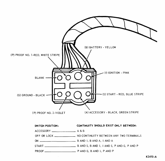
Here’s the color codes and functions of the 1970 ignition switch:
http://www.rccinnovations.com/Temp/1970_Ignition_switch_wiring.png
Note that this is the connector at the end of the ignition switch pigtail, not the switch itself.
Oh thx Bob! First time I have seen the violet wire! ![]()
What is Proof 1 and Proof 2?
Bob - where does your relay get 12 volts for the igniter?
I believe Proof 1 and 2 are the ‘prove out’ circuits for warning lights, etc.
The 12V comes from the battery.
https://www.rccinnovations.com/Instructions/Pedapter_Instructions.pdf
https://www.rccinnovations.com/Instructions/P00x%20install.pdf
What am I looking for with the test light? Light during crank AND run? Just crank or just run?
Hot during both crank and run.
If the pink wire is only hit during run - this is the resistor wire? Did you say “don’t mess with the resistor wire”?
The wire transitions from regular wire to resistor wire. The resistor section is fatter and is usually covered with a sort of woven, cloth like insulating sleeve, it then transitions back to regular copper wire. Do not attempt to splice into the resistor part.
The plan is new dizzy and coil from Pertronix - D134610 and 40011. Pertronix I igniter and Flame Thrower I coil. And probably their power relay as well.
If they offer an Ignitor II option I would get that. One other advantage of the Igntor II is that it won’t be effected if you leave the key in the on position without the motor running.
As Bill and I suggested you’d be much better off with the Ignitor II.
he next level has 4 times the energy of points between 3000 and 5000 RPM operating at it’s full potential working with 12 Volts and features Adaptive Dwell. I would recommend however you check the available voltage at the coil with the ignition on to check the health of your resistance wire before making a choice. An Ignitor II low resistance coil is recommended. Ignitor II 45,000 Volt coils are .6 ohms resistance and available in chrome or stock looking black. The Ignitor II units also operate off of a magnetic wheel that mounts underneath the rotor.
I have about 7.4 volts at the + side of the coil during run
Thx Bob. Which relay would you suggest for me? 001 or 002?
If you want to bypass the resistor wire to get 12V at the coil go with the 001.
Very confusing. ![]()
I thought the goal was to get twelve volts to the igniter?
Again, this is the ignition switch side of the ignition switch connector, where wire colors do not necessarily match what is on the main, underdash harness. Most of the ignition switches have pink wires instead of the red/green or green/red wires found on the underdash harness. You do not want to tap into the wires coming from the connector to the ignition switch itself if you can at all avoid it.