In that case either one will work.
So why not tap in after the firewall, on the engine side?
Ok, so there are two schools of thought? Either 12 volts to the coil or 12 volts to the igniter that in turn feds the coil?
The most common lead that is RUN-only (both RUN and CRANK) is the coil line (red/green) but after the firewall, it has the resistor wire in it. On a 70, there is another RUN-only line which is the large white female bullet part the firewall with a bluish-green colored wire that was used for the anti-stall feature on the carb. This line is fused, so if your fuse blows, the car won’t run. Another RUN-only line is the green/red line going to the alternator plug.
Not schools of thought. Physics. It’s ohms law not ohms suggestion. If your coil is not rated for 12 volts you will overheat it. In any event if the resistance is too low you can burn up the key switch and or tach unless you use a relay.
I think I’ll just use a relay. The tech support folks at Pertronix seem pretty knowledgeable.
You guys are as well. But there are too many iterations for me to know what’s best for my car, with no tach, and no red green wire.
Aside from 40 years in automotive electronics I interviewed the engineers at Pertronix and then wrote tech articles about the products that were approved by the engineers. Those engineers bemoan the terrible marketing materials and very poor tech support docs on the site. They have begged for a rewrite of the basic instructions because they are misleading. If the engineers are frustrated how could it be any different for you? What I can say with absolute certainty is that these electrical devices will behave in accordance with Ohm’s Law in every case and that is what I have tried to impart.
I should add that after I published the first article they asked me to write additional articles for other groups, specifically Ford trucks. As it turns out, that resistor wire is a mystery to more than just Cougar enthusiasts.
Bill:
For the unaware, the Pertronix II really did a job on the factory’s current sensing tach. Pertronix supplies nothing in the box about them. I use a Scotchlok and pulled the 12V feed before the tach and out through the firewall via the engine harness boot. It takes sharp eyes to detect.
It works with no issue at all. The worst part of the job was pulling the cluster.
-Keith
My current set up with the Mallory distributor and igniter, MSD Blaster 2 coil also worked with no issues.
Until it didn’t and I needed a tow back home. That is what I am trying to avoid. My points NEVER stranded me. I’ve owned the car since 1979.
All the info about ohms and amps and current and voltage is all very interesting. But I’m not an engineer. I’m not probably gonna do all that math. I just want to maximize performance AND reliability, while knowing I’m not burning out the igniter or the ignition switch.
As a side note, the Pertronix power relay instructions seem very straightforward with one caveat. And that is if you are running the car and turn the key off, and it continues to run - you need to install a diode in the wire to the I connector on the voltage regulator. They suggest soldering the diode in place.
But… if your alternator charging light does NOT come on in the ON position, then you have installed the diode backwards. No real guidance that I can see about how to instal it correctly. So what then - unsolder, turn it around and re- solder? ![]()
Again, not an engineer, but it really shouldn’t be this difficult.
1 Like
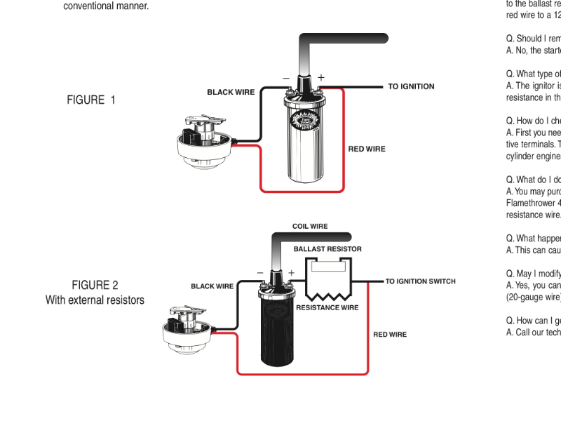
For my engineers - here are two screen shots from Pertronix instruction manuals for the igniter/distributor and their power relay.
One shows the igniter red wire BEFORE the resistor wire. The relay shows the connection AFTER the resistor wire. Can someone explain that? Thx
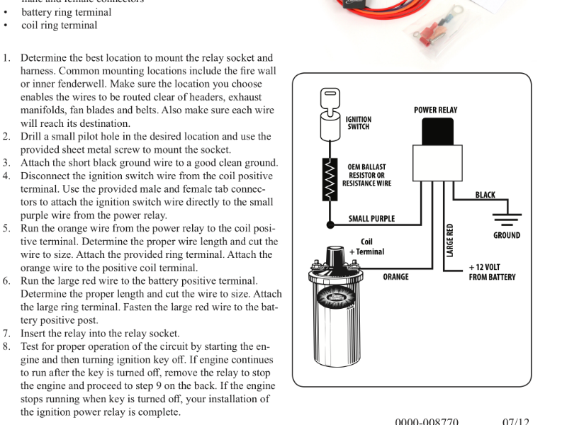
Yes. They are using the power from the ignition switch through the resistor wire to “trigger” or switch on the relay which lets 12v flow from the battery to the coil.
Thx.
Do both applications, with or without a separate power relay, accomplish the same thing WITHOUT burning out the ignition switch?
My confusion is one method enters the system BEFORE the resistance wire and the other AFTER the resistance wire.
Read the instructions next to the illustration. Some vehicles don’t have a resistor wire or ballast resistor so the coil is supplied with 12 volts. Your car does use a resistor so you need to follow the diagram that matches your car.
For anyone reading this thread in the future, here are some easy installation instructions for my Pedapter kit:
- Follow wire from coil + post back to the flat (three wire) connector at firewall.
- Unplug the connector, plug the Pedapter box into factory connectors.
- Run RED wire from Pedapter to battery positive (red, +).
- Connect BLACK wire to ground (black, -).
- Connect orange wire to Ignitor.
No locating start/run wires. No locating and avoiding the ballast resistor or resistor wire.
Both kits provide a switched 12V wire under the hood that can be used to power an Ignitor or other component(s).
Differences:
P001 = 12V to Ignitor and options to provide 12V to coil or disable ignition completely.
P002 = 12V to Ignitor
The P001 & 002 come with a run-on diode as well. I have never heard of anyone having to use it, but I include a picture showing the correct orientation of the diode in case they ever do.
Both versions use 60A weather proof relays in a sealed box as well as a fail safe ‘limp mode’ that will keep the the Ignitor powered if the relay ever fails in which case the P001/002 will be replaced under warranty.
Thanks Bob!
Thx Bob.
So the orange wire from the Pedaptor is connected to the red wire from the igniter?
Both Rocketmans relay and Pertronix relay enter the circuit after the resistor wire.
The difference I see is Bobs pedaptor goes to the igniter. Pertronix relay goes to the + side of the coil.
Is the net effect the same? In either case, is the coil AND the igniter getting 12 volts?
The relay isolates the key switch. All of the current driving the coil passes through the relay. You have to use a 12 volt coil and you should use the Pertronix II to handle the increase in power. Note to readers with factory tachs: this wiring method won’t allow your tach to function. You will need to get the Rocktman 3 wire tach.