Ignition resistor wire

Bill,
Can you review and provide a quick response to the two questions below.

"Poor choice of words when I said bypass. So you tap into the ignition wire prior to the resister wire and run it directly to the Pertronix. Remove the points and run the black wire of the Pertronix to the coil. Leave the positive side of the coil as is and the tach will operate as normal?

So using a full 12 volts to an Pertronix I will allow use of the stock coil without any failure problems? I have ran a Pertronix I with the proper Pertronix flame thrower coil without failure on the resister wire. I have a Shelby 68 GT-350 in my shop now. I plan to follow your thoughts and provide a 12 volt source to a Pertronix I and based on your answer to the above questions, use a stock Autolite yellow top coil."

Rob


Thx Bill. There are many references to a “12 volt coil”. Here is a screenshot of specs on the Pertronix Flame Thrower coil. I see no reference to 12 volts. I guess I assumed 12 volts was a “standard coil”, whatever that is.

Yes, using the stock coil with P1 works great. The P2 will also work and provide immunity from key on engine off failure

When you run higher voltage in the coil you get more power. More power equals more heat. Coil failure usually comes from overheating. Pertronix does a terrible job of explaining this. They only hint at this in a few charts. Theoretically their coils might run at 12 volts but in my experience you are risking failure.

Ok, thx but more confusion.

I thought you said I needed a 12 volt coil, whatever that is?

Do we want 12 volts to the igniter? 12 volts to the coil? 12 volts to both? This is the coil recommended for the distributor. Is the Flame Thrower a “12 volt coil”?

Now 12 volts is too much?

Very confusing. Appreciate your patience.

What do you mean “stock coil”? Original black with the yellow top? Or this Flame Thrower coil? Thx

I thought the whole idea was to bypass the resistor wire and get 12 volts to the coil, or the igniter, or both?

No? If I ever get it, I’ll upgrade to the Pertronix set up. Until then, I have to stick with the Mallory. Now I’m afraid of burning up the coil, or the ignition switch, or both.

There is no real mystery here. It’s super simple to do and worth the effort.
-Keith

That made me lol.

I’d the Pertronix engineers are confused, I don’t feel so bad.

The Ignitor in every case is a 12 volt device. Always run 12 bolts to it. If reliability means anything to you leave the resistor wire intact and run the stock coil or the Flame thrower coil with 1.5 ohm resistance

For what it’s worth, I have never seen any verifiable proof that running 12 volts yo the cool results in a measurable improvement in performance.

I wouldn’t say “confused” but Bill will tell you the same thing I will. They know nothing about the current sensing tachometers Ford used. I think a few people have tried to assist them. It’s simple once you’ve done it… It’s really a simple procedure period. It’s a matter of running a single 14 gauge red wire to the red wire from the module that is 12V ignition only power. The negative is mounted under the - on the coil with a nut and the negative from the engine harness slid onto the same negative post.
-Keith

So you are discussing 12 volts to the coil with your “red wire”? Bill does not seem very fond of 12 volts to the coil.

Do you have 12 points to the igniter?

It looks like Rocketman’s relay gets 12 volts to the coil AND twelve volts to the igniter.

The Pertronix relay only has one wire to the coil.

12 volts. My bad. :stuck_out_tongue_closed_eyes:

It really is simple.

When talking coils we are talking stock style canister coils. Coil packs, GM HEI coil in cap and modern (post 2000 to be safe) coils are NOT included.

You have OEM (original equipment or ‘stock’) and Aftermarket (Pertronix, MSD, Accell, etc).

All of the OEM coils are made to be used with an external ballast resistor - be it ceramic or a resistor wire. FoMoCo (Ford Motor Company) chose to use the resistor wire in our cars. The general rule of thumb is the input voltage at the coil is about 1/2 the system voltage.

This is fine, but current through a conductor = heat and heat = resistance so in very high RPM situations the input voltage could drop and cause misfires.

One solution was create a coil that would accept full battery (b+) voltage (commonly called 12V). These coils are not widely used in street applications and will not run well with reduced voltage.

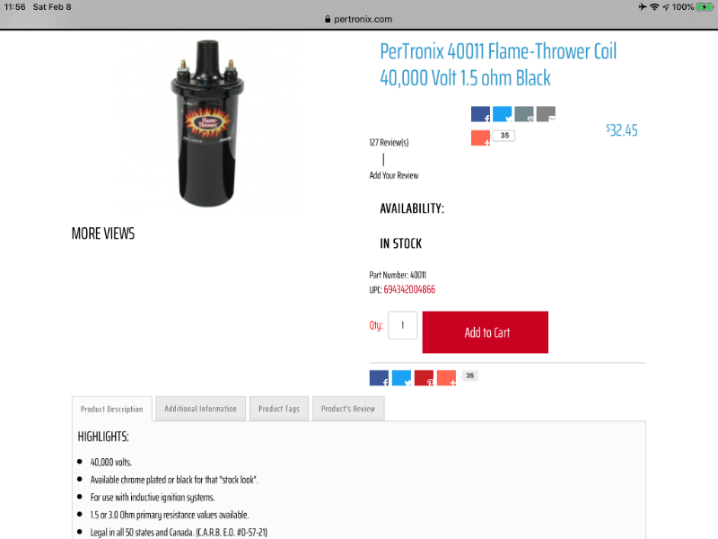
The most common aftermarket solution was to reduce the normal internal resistance from 1.5 ohms to 0.7 and in some cases 0.3 ohms. These coils also have more windings and the good ones use heavier gauge wire as well. The lower resistance and additional windings result in a higher voltage discharge or spark.

Most OEM canister coils are marked as requiring an external resistor - like my OEM Duraspark coil is.

ALL coils requiring 12V should be marked as NO BALLAST coils and NOT include a ceramic ballast resistor. A 12V coil with a ballast resistor will run like crap - especially at idle.

Last I knew Pertronix coils came with an external ceramic ballast resistor. I believe that they do this because their products are designed for performance vehicles that probably do not have the original ballast wire anymore. It is up to the end user to decide if they need it or not. The fact that it comes with one tells you that one is required somewhere in the circuit. If in doubt, ask the manufacturer if they supply or recommend an external ballast resistor with their coil.

So, unless you are running a high performance aftermarket (or late model OEM or GM HEI) coil, you don’t need 12V to the coil input.

Now, for the IF:
IF your OEM resistor wire has failed or someone has removed or bypassed it, you will need 12V to the external ballast resistor that is normally mounted beside/with the coil.

As far as the Pertonix Ignitor: All three SHOULD have 12V. Some folks swear that connecting a series 1 to the coil + post works fine and they might, I don’t know because I have never wired one that way.

As stated earlier the P001 has the OPTION of 12V to the coil, both the P001 and P002 have a switched 12V wire for the Ignitor.

That’s because they want 12V going to their Flamethrower II and III coils.

From the Pertronix website (bold is mine):

Most pre-1974 vehicles are equipped with OE resistance wires which limit the current for breaker point operation. PerTronix’s Ignitor II and Ignitor III ignition systems require a full 12V power connection between the ignition switch and the positive coil terminal. This requires bypassing the ballast resistor or resistance wire. In many cases, the original resistance wire is buried in the vehicle’s wiring harness. Adding a PerTronix power relay will eliminate the need to dig through the wiring harness and replace wires. Plus, the power relay guarantees maximum system voltage for more power.

See, the manufacturer says right there that those two coils DO NOT use a ballast resistor, therefore they are 12V coils.

All of your questions have been asked and answered. You are over thinking this. It would probably be best to decide WHAT you want, then read the instructions (not just look at the pictures) that come with the components. If you have questions specific to your build then we can give you specific answers.

My thx to everyone.

The 12 volts go to the red wire on the ignitor, not to the coil. The black wire from the ignitor goes to the coil. There is no need for a relay.

I think we all understand that by now, I think the question was where should the 12V come from, which has been explained very well from the above threads.

It would depend on if the vehicle has a tach. That changes where it should be pulled from. Now if the fact I commented on the subject because I have actually done it that would be your issue. Perhaps I should just stop commenting here period.