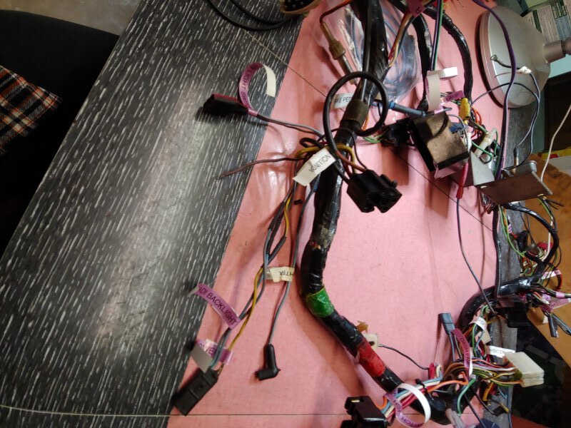
I am cleaning and repairing my various wire harnesses before I reinstall them in my 68 Standard (non-XR-7). I have a stray wire that needs a home. It is a brown wire that is a single solid wire and not a normal stranded wire. The wire is in the breakout area where the ignition switch/radio power/cigar lighter/and circuit 19 light 3 pin connector come out of the main harness. I am surprised it is a small gauge solid wire and not stranded. I suspect it pulled out of the ignition switch connector but can’t really tell. See the photo below. Can anybody identify this wire, where does it go and what is its function?
Looks like I figured it out. My old eyes and faded wire colors are to blame. It looks like the wire does go to the ignition switch on the “A” terminal as wire # 904 which is supposed to be Green with a Red stripe. Boy that wire jacket certainly has faded as it looks Brown to me and could even pass as Black. Wonder when I cleaned the wires, I removed the color. Anyways I found it since there are supposed to be 2 wires on that terminal, Wire #297 (Black with Green stripe) and wire 904. Still surprised it is a solid wire and not stranded, but the wiring diagram shows wire 904 is a resistor type. Glad I downloaded the diagrams from WCCC, they have been very helpful figuring out my mess! Now I have to get a pin extractor to remove the pin from the connector. I guess I will add another tool to my stash.
Don’t remove the pin if you don’t have to. There are no replacement big pins for the ACC and BATT lines in that connector plug. Instead, simply cut the black/green thick wire and splice the single strand resistor wire in one side and butt-splice the black/green wire together.
Are you going to run a points dist or electronic? If points keep the resistor wire. If electronic, replace it with a standard wire. The reason is, when you rev a electronic dist up the resistor wire drops the voltage to a level below what electronic dist need. Min 8V -14Vs.
I didn’t replace mine when I had it out for cleaning and had to run a jumper wire. Makes a big difference.

Midlife and Rickyracer thank you for your replies. What you stated makes sense since I know at some point a previous owner had installed a MSD ignition box as evidenced by the mounting hardware that was left installed. The box was removed prior to me buying the car. I always thought it was the Pink resistive wire 16A that required changing to a regular wire when using a MSD box. I am planning on running an electronic distributor of some sort and ditching the points.
Edit - After looking at the schematic again it appears my wire in question #904 is actually part of the voltage regulator circuit and not associated with the coil/ignition. I am converting over to an aftermarket 130 Amp alternator that is a 1- wire type so I will be bypassing the regulator wiring anyways. Going to the large alternator to power EFI fuel pump and electric radiator fans.
wiring.pdf (820 KB)
I use a 1 wire alt and the electronic ignition system and found the standard Cougar wiring (68) to be lacking at anything about 1500 rpms. I just didn’t put enough volts to the + side of the coil to power the system up. 16A is your resistor wire, 16 goes to the coil. 262 is from your staring current, brown wire.
I ran a seperate wire to the #35 wire in your diagram since when you go to the 1 wire alt, that 3 plug connector, on the regulator side of the plug, since it won’t be used anymore. My alt goes straight to the battery.
The #35 only has power when the key is on, and it gets the full power from the Alt. On a 72 Comet GT 302, I just jumper from the alt, (factory setup) to the voltage regulator using the Green/red
wire straight to the starter solenoid.
Rickyracer - thanks for the additional information. My goal is to remove the regulator and all associated wiring from the harness when converting to the 1 wire alternator and also make the harness compatible with an electronic distributor most likely with a MSD type ignition box. Appreciate your help. Jim R.
You might need the regulator, depending on your system, so as to not provide to much power. My alt will put out 14.6 volts all the time. The only way I found a problem was to check voltage at the + side of the coil while running it at all RPMs. Electronic dist like 8-16 volts at all times. Points dist need the resistor wire to survive.