Please help! ![]()
I have a 68 XR7, new battery, new alternator, new voltage regulator,new alternator harness and belt is tight. I’m not great with electrical but I have checked all the wires going to the voltage regulator as follows: field terminal on alternator starts off orange(35) and goes to white (35) at the plug from there I hooked it to the “F” blade on the voltage regulator. At the voltage regulator green with red stripe wire (904) is on the “S” blade and I followed it to the ignition switch. The yellow (152) wire goes from the battery side of the starter solenoid to the “A” blade on the voltage regulator. I have checked continuity on all wires (35) (904) and (152). “I” blade is not used.
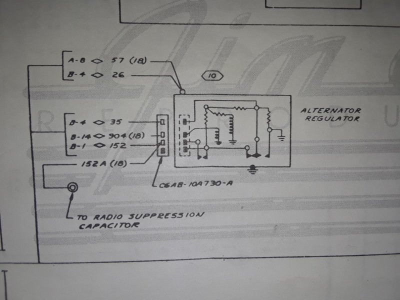
I will add this, the electrical manual does not label the blade connections of the voltage regulator but It looks like the white(35) white wire is hooked up to the “I” blade and the (904) green red stripe on the “A” blade and the (152) yellow wire on the “S” blade of the voltage regulator and “F” blade is not used. the reason I say this is because of the gap between the (35) and (904) wires in the drawing, see photo.I hook up my multi-meter and volts go down when running and come back up when I turn off motor. I need help at this point, I don’t have any more hair to pull out!
I had a problem which sounds similar to what you are describing. Ended up being a bad plug at the end of my under hood harness where it connected to the alternator harness: https://cccforum.discoursehosting.net/t/68-xr7-charging-system-problems/11019/1
BigCat
Since you have an XR7, the wiring you described is correct. Note the XR7 uses an ammeter whereas the standard uses an idiot light.The electrical manual with circuit 35 going to the I terminal is for idiot light systems.
In the diagram you posted, the circuits at the regulator are as follows:
35 - F Field
904 - S
152 - A Battery
Although you tested for continuity on all 3 circuits and proven them to be good, you need to turn on the ignition switch and verify that 12v power is present at the voltage regulator’s S terminal. If there is no power here in the run mode, then the alternator will not “turn on” and excite the alternator’s Rotor field coil.
Also check your wiring at the alternator and make sure the Black with Red stripe wire (which is the Ground wire), is clean and properly grounded. If it is corroded or not attached, it will also cause the alternator to not “turn on”.
I assume you are using a solid state regulator, if not well . . . Why NOT??? Sorry I’m a little punchy today, yes mechanical regulators work but they need to be adjusted. I removed my mechanical regulator and replaced it with the Solid state version years ago.
Last but not least, you can take the remove the alternator and have it bench tested at a local auto store.
Let me know if you need any additional information
Coach Jack
Coach Jack,
I pulled the harness plug off the voltage regulator and with the key in run mode I do not have 12v at the female end of the (904) wire. I am using a solid state regulator. I will double check the alternator ground wire at the block. although I did get continuity between the fender hardware and the body of the alternator.
Im sure the ground is connected to the alternator body on the back of the alternator.
The only thing I personally would have to add is a good case ground on the VR and clean and completely inserted spades at the VR plug in. They can work their way back a little sometimes, and/or get rusty and not make contact.
BigCat,
Hmm, if there is no power on the 904 wire, yet as you stated in your original post there is continuity from the ignition switch 904 circuit to the voltage regulator, you need to test the ignition switch and make sure that the ignition switch’s A terminal (Accessory) and B terminal (Battery) have continuity in the run position. If you don’t, then your switch is bad.
BTW, I didn’t ask in my previous reply, but why did you replace the alternator, voltage regulator, alternator harness and battery in the first place? I’m just curious if things worked before or not.
Coach Jack
Coach Jack,
Thank you for instructing me to check the switch. Yikes! I think I have a big mess. Please look at the photos. Pretty sure I need to start over, what do you think? 904 wire looks to in the “po”. I left my meter prob in the socket that I have continuity with 904 at the voltage regulator. The reason for all the new stuff is when I put the motor in the car the alternator bearing went out, 7 year old battery went dead,it had a scabbed together alternator harness and while I was at it do the voltage regulator.
BigCat


BTW, the car ran fine when I bought it and even now, I did not do the wiring on the switch but I did pull the entire under dash harness out and fixed all the splices and pulled out about 7 of those blue plastic wire tap connectors.
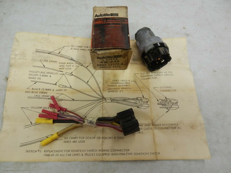
NOS Autolite ignition switches come with that connector. They are not hard to find, all over eBay typically around $45.
Thank you Royce,
I’m not sure if I just need the key switch part or if I need to rewire the PO’s work. I wish i had a better view of that chart and wire diagram! but that’s not a lot of money. Do you know if the 68 XR7 should have the pink resistor wire?
Yes, it has a pink resistor wire which may be anything from pink to brown depending on if anyone has put too much current through it over the years. It runs from the connector at the tachometer to the firewall on XR-7’s. If the car was a standard Cougar it would run from the ignition switch connector to the firewall.
BigCat,
I pulled my spare 68 xr7 harness out and tested it to get a better understanding and help you troubleshoot your problem.
As far as the ignition switch wiring, it is hard to tell the colors of the red striped wires in your picture. My 68 harness as pictured from the back (matching your picture). Note if you are looking at the wiring diagram, the below is transposed left to right, as the wiring diagram is viewed from the front looking at the plug ends. Below is from my 68 wiring harness and is slightly different than that shown in the wiring diagram.
Top left - Black Green striped wire - Circuit 297 Accessory - Feeds fuse box Acc and heater fuse in fuse box
Top Right - Violet wire Circuit 977A - Prove out circuit to brake failure switch on Master cylinder
Center - Yellow Circuit 21 - Input power from B post of starter solenoid
Lower left - Red Blue striped wire - Circuit 32 - S post of ignition switch to S post of starter solenoid.
Lower right - Red White striped wire - Circuit 39 A second Prove Out circuit for xr7 models to dual brake warning light
Lowest center - Red green striped wire - Circuit 16 - Note on the harness I tested, this circuit splices in with both the tach circuit (and eventually the ignition coil circuit) and the Voltage regulator Circuit 904, whereas the wiring diagram shows circuit 904 connecting to the A terminal of the ignition switch.
Interestingly enough, you said your car starts and runs (which shows that circuit 16 is active). However since my harness also is spliced in with circuit 904, did you by chance remove this when you were rehabbing the under dash wiring?
A couple things that puzzles me, your picture shows that circuit 904 is connected to the lower left wire which is the other PO (Prove Out circuit). It should connect to the C post of the ignition switch. You should trace these two wires (circuit 16 and your circuit 904 ) to see where does the red green circuit 16 go and if you had removed a splice and the green red wire circuit 904 for any splices that you may have added.
Coach Jack
Coach Jack,
That’s just what I needed. I will get home tonight and follow every circuit then report back. I did order the NOS switch and harness that Royce provided the ebay listing. One of the clips on mine is broken. When you suggested to check for continuity between A and B on the key switch in the run position is when I found the 904 in the “prove out” so that explains why the alternator is not charging. right?
Some more info: The car came with a pertronix coil, and an aftermarket tach. I pulled the tach out. I wanted the stock tach to work and sent it to Rocketman. I have the tach wired to Rocketmans wiring diagram using the pertronix coil scenario and it works fine. When I fixed all the splices and cuts in the main harness I fixed one wire at a time and am very sure I put it back the way it was. There was a mystery wire that I got rid of thinking it was part of the aftermarket tach, because it went up to the coil area but I don’t remember exactly where it was connected. Thank you for taking the time to list the connections on your spare harness. On the up side, I understand how to read a wiring diagram much better than before ![]()
BigCat
I found the 904 in the “prove out” so that explains why the alternator is not charging. right?
The 904 circuit must have power in the run mode whereas the PO (Prove Out) circuit in the ignition switch provides ground in the start mode. The 68 Cougar wiring diagrams show that 904 connects to the A post (Accessory) on the ignition switch , where as the 68 XR7 wiring diagram shows it connects to the C (Coil) post on the ignition switch. As I pointed out in my previous post, the 68 xr7 wiring harness that I tested using a multimeter is spliced within the harness to circuit 16 which attaches to the C post. However the 904 circuit gets routed, it must provide power to the 904 circuit at the S (Stator) connector on the voltage regulator to turn on the Alternator. The voltage regulator has 4 prongs, F (Field), S (Stator), A (Battery) and I (Indicator). Because the XR7 uses an ammeter, the I terminal is not used.
There was a mystery wire that I got rid of thinking it was part of the aftermarket tach, because it went up to the coil area but I don’t remember exactly where it was connected.
Can you tell what color the mystery wire was? According to the 68 xr7 wiring diagram, the tachometer has 2 connectors and 3 wires, the pink wire (tachometer output) that feeds the coil, and the red green striped wire (tachometer input) from the ignition switch C post (as noted above) spliced with a red yellow striped wire that provides power to the dual brake warning light.
Coach Jack
Coach Jack,
I checked the wiring and found the 904 was in the prove out spot. With a new harness coming I decided to just remove the one installed. The mystery wire was a shiny new blue wire that was for sure added by P.O.
I could try and reuse the stuff I have but will wait for the new parts. Please see photo. So I should be able to hook it up as you described below?:
Top left - Black Green striped wire - Circuit 297 Accessory - Feeds fuse box Acc and heater fuse in fuse box
Top Right - Violet wire Circuit 977A - Prove out circuit to brake failure switch on Master cylinder
Center - Yellow Circuit 21 - Input power from B post of starter solenoid
Lower left - Red Blue striped wire - Circuit 32 - S post of ignition switch to S post of starter solenoid.
Lower right - Red White striped wire - Circuit 39 A second Prove Out circuit for xr7 models to dual brake warning light
Lowest center - Red green striped wire - Circuit 16 - Note on the harness I tested, this circuit splices in with both the tach circuit (and eventually the ignition coil circuit) and the Voltage regulator Circuit 904, whereas the wiring diagram shows circuit 904 connecting to the A terminal of the ignition switch.


BigCat,
It is hard for me to tell the color of the wires in your photos. Please confirm the wires, I assume that the 1st picture shows from left to right a violet, green red striped, red blue striped, red with an unknown color striped (my guess is that it is green striped), black green striped and I assume yellow.
The second photo from left to right red blue striped, black green striped, red with an unknown color (my guess is green), yellow, violet and red with an unknown striped color (my guess is white striped ).
What we do know since you stated that the car starts and runs is that the Yellow (Battery) wire, the Red blue striped (S starter trigger wire), Red green striped wire (C ignition circuit) are all in their correct positions. I assume that the black green striped wire (A Accessory) is also in its correct position since only the yellow and this wire are larger gauge than the rest.
My question now is your 1st photo shows a green red striped wire (presumably the 904 wire connecting to the Voltage regulator’s S terminal). Was this connected to the Red white striped wire on your ignition switch? Verify the 904 with a multimeter, if it indeed is, I would splice this into the red green striped C wire and just tape up the red white striped wire and leave it disconnected.
Coach Jack
Coach Jack,
Sorry about the photos being “washed out” but you are correct on all the colors.
The green red strip wire was in fact connected to the red white strip wire. I will double check continuity today of the green red strip wire with the voltage regulator.
I will have the new parts on Tuesday. The condition of the existing plug is questionable with bare wire at the base of the black green stripped wire and broken clip.
But I do understand your instructions and will fold back and not use the red white strip wire on new harness. And connect green red strip wire with red green strip wire and connect both of those to the red green strip wire on new harness.
Thank you to everyone in advance especially you Coach Jack. I will let you know how it turns out.
FIXED!!!
Now charging, my meter shows 14.50 volts at the battery while running. That seems kinda high to me but I do have the higher output alternator.
Thanks Royce for the link to the part and Thank you Coach Jack for walking me through the troubleshooting.
BigCat
Glad to hear you got her fixed. 14.5 volts is normal charging voltage.
Now go out and enjoy your ride!!!
Coach Jack