Hi all. I received my Pertronix 1 and Flamethrower coil yesterday, and would like to install it this weekend. I have read quite a bit on the topic (especially xr7g428’s excellent post from a couple of years ago). However, being a total rookie at this I am left with a couple of questions.
From my research I understand that I am to run a new wire that I purchase separately through the grommet in the firewall using a brass tube. I got that part. What’s confusing me is what and where I am supposed to attach the wire. The post says to attach it to the red and green wire for an XR7 with a tach. Mine is a standard, so no tach. Does that mean I attach it directly to the pink wire under the dash? Under the hood I’m to attach it to the red wire on the Pertronix. That seems simple enough so no questions there.
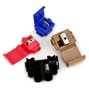
Also - and this is a little embarrassing - how exactly do I go about attaching the wires at each end (under dash and under hood)? Is there a special connector I should buy? Is there splicing involved?
That’s all the questions I have (for now). Thanks a bunch to all for your help.
I presume this wire is for the Petronix power, which needs a RUN-only signal at full 12V. Most Petronix 1’s work well off of 9V, so power comes directly from the + side of the coil, even if you are using a resistor wire. If that line has to be run into the engine compartment, snag the green/red wire coming off of the ignition switch, which is RUN-only 12V before or bypassing the pink resistor wire.
Ok so it’s the green/red wire. I haven’t looked closely at the wires coming from the ignition switch so I misinterpreted what I’d read and assumed only tach equipped cars had the green/red. Thanks for clearing that up man!
Do you have any guidance on how to actually connect the wires?
You can run power directly off the + terminal of the coil for the Pertronix 1 install. The Pertronix 2 &3 will either need the Rocketman relay or the Relay from Pertronix. The Red/Greeen wire should be running to the + terminal already. Still, better to be safe than sorry and ask if you don’t know. Ditto for the Flamethrower distributors. They need a relay to supply the full 12v to the distributor.
Thanks. So for clarification, when you say “run power,” you’re referring to the new wire (the one I buy separately)?
As far as where that new wire connects, you’re saying it goes from the red/green wire at the switch to the + terminal on the coil (not to the red wire on the Pertronix module)?
To clarify, I have a base model 289, no tach, and the power wire that connects to the coil positive terminal is green/red, so connect that as well as the red wire from the Pertronix module to the positive terminal of the coil, and connect the black wire to the negative terminal at the coil. Like I said, mine is a 289 base model w/ no tach so maybe a big block owner will chime in.
On splices I strip back about an inch on each wire and braid them together, and put a twist close to the insulation so it looks like the two wires are seam less instead of like an electricians job. Kind of looks like you just stripped the insulation off of a section and didn’t cut the actual wire. I then solder and use heat shrink to cover it. Always put the heat shrink on first and then slide it over once the soldered splice cools and heat it until it shrinks around the splice. Then you don’t have to worry about a failed connector, and it looks much nicer than a butt connector. I’m not sure if this method actually gains anything over a connected splice amperage wise, but gives a good strong connection and the solder joint won’t come apart like a connector. Would be a pain to do under the dash though.
I know it’s a little anal retentive, but I like things to look nice as well as work.
Yeah, mine is a base model too so I’m running sans tach. I probably should have just worded the question “after I buy the new wire, what do I connect it to at each end and how do I physically make those connections?” Would have made it easier for all involved.
Look, the Pertronix 1 is a 12 volt device. All Pertronix are 12 volt devices. That they can run for a while on less voltage is testament to the quality of the part, but you are asking for failure.
Here is what you need to know: voltage divided by resistance equals current in amps. The stock ignition has two resistors in series: the resistance wire and the coil. They are each about 1.5 ohms or higher. You add resistances in series together so you get 3 ohms. Twelve volts divided by three owns gives you 4 amps of current draw through the circuit. The key switch is designed to handle a bit more, maybe 6 or 7 amps max. If you bypass the resistance wire you drop the total resistance to 1 1/2 ohms. Twelve volts divided by 1.5 equals 8 amps of current. This is too high for the key switch and it will get hot and then ultimately fail.
The stock coil had an internal resistance of about 1.5 ohm and was designed to run on about 6 volts. The resistance wire is what reduces the voltage. If you get rid of the resistance wire the coil now sees 12 volts and it will overheat and eventually fail.
When you measure the voltage at the coil, if the points are open, or the Ignitor is open, then you are going to read the voltage across the meter. You will always read the highest voltage across the greatest resistance, and in this case it is the meter itself. If the points are closed or the Ignitor is conducting to ground, then you will read the correct voltage. The best way to do this is to measure with the engine running.
All of this is Ohm’s Law, not an opinion. If you want things to work reliably you have to do it correctly. There are no extra parts that you can just ignore or leave out without some consequence.
Use a relay if you are going to run a low resistance coil. Run a separate power wire from a 12 volt source (hot during start and run) to power the Pertronix or any other electronic ignition that say s it needs 12 volts. A relay can also serve this function. If you don’t know what all this means get a Pedaptor from Rocketman’s Cougar Innovations, wire it as instructed and you can’t go wrong.
"All of this is Ohm’s Law, not an opinion. If you want things to work reliably you have to do it correctly. There are no extra parts that you can just ignore or leave out without some consequence. [/quote]
Definitely not trying to leave out any parts or skip any steps. I am a rank beginner at this and have zero experience with automotive electrical systems. I thought your post from 2014 laid things out very well and it was a great starting point.
However, some of the replies to this post confused me a bit so my questions were for clarification so that I can (and will) in fact do it correctly.
I probably come off pretty preachy on that… sorry about that. I have spent time talking with the engineers at Pertronix about this and they are very frustrated by the confusion in the market. I keep telling them that the instructions they publish are also a big source of that confusion.
I initially had my Pertronix connected per the instructions (+ and - terminals on the coil) (69 XR 7, 351W). The engine would run fine, but would occasionally stall at idle due to the combined voltage reduction from the resistor wire and voltage drop at idle speed (~6 volts). I did some poking around and found a wire on the voltage regulator that would work to supply constant 12V during start and run and have used that source for many years with no problem. Sorry wouldn’t know which wire it is at the moment. Adapted the connection into the adapter harness for my 92 Mustang internally-regulated alternator.
Wow. I never had a problem running a Pertronix 1 directly to the coil. That beings said, the Flamethrower distributor with Igniter 3 internals would not idle after 20-30 run time without a relay to give a full 12v. I guess I just got lucky. Glad someone else chimed in and saved another enthusiast the headache I had with my igniter 3.
No argument on the basics of ohms law. However, the resistor wire heats up when current flows through it and the resistance rises. This wire acts as a current choke. Typical measurements at the + side of the coil while the engine is idling is 11.5V while the battery is 13.5V. This tells me that the current flowing from the ignition to the coil is more like 1-2 amps at most. The internals of the Ford tach’s transformer is in line with this current path, and that transformer certainly can’t handle 4-8 amps for long duration.
Can’t argue with Bill on this one. He’s absolutely right that Pertronix’s instructions are the biggest source of confusion when it comes to the voltage demands of their devices. When I had the problem with my Flamethrower, I went back and looked at the instructions, and at least on mine, the note that I would need a relay for 12v ignition supply was AFTER the actual installation instructions.
The easiest thing to do would be to have an all caps note in larger font and bold type stating the need for 12v and give at the very least a year range of cars that do NOT supply 12v. Wow, I probably have more than one person who bought a car I sold with the Pertronix conversion pissed at me for selling them a car that won’t idle in traffic as the engine keeps running.
Ok guys I think I’ve got this figured out. I just came out from under the dash and I see what looks like a pink wire running to the back of the key switch. The only red/green wire connects to a little block at the top of the brake pedal lever/arm. I assume it’s the pink one that I want to connect my wire to. Correct?
To determine voltage across a resistor, in this case the coil, you first need to determine the current, which is the same in every part of the circuit. To do this you use this formula Current = voltage / total resistance. So with a fully charged battery in perfect condition we have 13.6 volts. The resistor wire is about 1.5 ohms and the coil is about 1.5 ohms, so total resistance is 3 ohms. That means we have 4.5333 amps of current at every point in the circuit. To find the voltage across the coil you multiply current times resistance. So 4.5333 times 1.5 is 6.7999 volts. In the real world that is going to be about 6.5 volts.
So why do people see higher readings when they measure this? If the points are not closed, the circuit is not completed. So the meter will actually show the voltage across the meter to ground and the internal resistance of the meter is much higher than the rest of the circuit. You always measure the highest voltage across the greatest resistance. If the car is running, the points are not closed all the time. Meters average this type of input, it is called the integration time, if you delve into the specs of the meter. The average voltage will be higher than the real working voltage of the coil.
The reason that our tachs do fail so often is that they are passing quite a bit of current. This is also why putting a lower impedance coil, like a .6 ohm coil, will kill the tach and heat up and then kill the key switch.