Can I hook the Pertronix to the stator on the alternator to get my 12 volts. That seems so much easier than finding another spot to hook it to.
Thanks
No. The STATOR puts out about 9V, IIRC, and won’t provide voltage until the engine is turning over. The distributor needs 12V prior to cranking for the engine to catch.
It has to be hot during both start and run. The stator actually only has output after the engine is running and the alternator is charging.
Make it easy on yourself. Is it a Pertronix I ? If so, it will usually run just fine with the Ford resistor wire in place. If you have a Pertronix II OR THE P-1 won’t operate correctly with reduced voltage, thenheres what you do. Get a 3 foot length of 12 or 14 gauge multi strand automotive wire and two blue scotch locks. Scotch lock the regular wire at each end of the resistor wire. voila . The current will travel on the wire of less resistance, i.e. The new wire, and in case you need to go back to points when your Pertronix goes belly up, it’s easy to remove the extra wiring and put the points back in and hit the road again.
Note: normally I don’t like to use scotch locks, but in this case they work great. The ni-chrome resistance wire is tough as nails and the scotch lock will get a good bite and yet not cut into it.
Z
Zray that is a very bad idea. I am sure that you have heard this at some time but it is one of those things that seem like a good idea until something breaks. The problem is that the ignition switch is only good for at best 8 amps. After 50 years probably a bit less. When you bypass the resistance wire you drop the total resistance in the circuit. That causes the amount of current to go up, and it can easily exceed the rating of the switch. The switches are kind of iffy to begin with. There was a recall back in the day because they were failing with everything completely stock. That is why you see so many switches that are connected with a bunch of butt connectors. Secondarily, for XR-7’s the factory tach is series with the coil, so you are pulling a lot more current through it as well. Aside from the obvious cost of a replacement tach, the car won’t run if the tach fails.
Here is what happens: when the car is running you should have about 14.4 volts. Current is voltage divided by resistance. The resistance wire is between 1.5 and 3 ohms. The coil should be about 1.5 ohms. Total series resistance is 3 to 4.5 ohms. So we have 14.4/3 = 4.8 amps current. Bypass the resistor wire and we have 14.4/1.5 = 9.6 amps of current. Now the switch won’t fail immediately, but it will start getting hot. If you have ever touched the ignition key and it was warm or hot to the touch you have experienced this.
The easiest solution is to run a new wire from the red with green stripe wire at the back of the ignition switch to the red wire of the Pertronix. Any of the Ignitors will sort of work with less than 12 volts but none of them are designed to do so. The original Ignitor I came with instructions that made it look like you could run it straight from the coil but that was only were the coil was being fed 12 volts and no ballast resistor was being used.
Does the Srator go dead when you turn off the key? If not then how would one turn off the engine?
With all due respect, your replacement of the resistor wire, and my bypassing it with a jumper wire attached at each end of it, both techniques result in the same exact amount of current flowing thru the switch. There is zero current flowing thru the resistance wire when a normal wire is jumping it. Current will ALWAYS flow on the wire of least resistance. So there is absolutely no difference as far as current flow and the resulting heat is concerned . The amount of current does not increase as you state, because the demand of the ignition coil determines current flow, and the flow is identical with the Pertronix as it is with the points ignition . The type of coil alone determines the current requirement and the current flow, not the placement of a substitute wire or the placement of a jumper wire, either of which are identical in regards to current flow. As far as the tach goes , tach operation is unchanged as well. I’ve wired numerous Pertronix I’s for my Shelby and K code customers as well as for my own Shelby’s and K codes, in this fashion. Both of which use the same type of tach and attendant wiring as do the cougars in regards to those having a factory tach. Ignition switches in all cases continue to perform as normal with no rise in temperature internally or at the connections.
I’m not trying to convince you of anything . I’m sure we will agree to disagree. Just pointing out my experiences in wiring the P-1 in this manner when, on occasion, a full 12v is needed.
Regards
Z Ray
PS
this is EXACTLY the same as running a jumper wire along the ends of the pink resistance wire. (the pink wire having its end in the connection to the red w / green stripe wire (#16) at the ignition switch.) The jumper wire is bypassing the pink wire just the same if it was wired around as you are suggesting
PPS your new wire is taking the resistance wire out of the ignition switch / coil / circuit just the same as my bypass does. So if my solution is making the current increase to unsafe levels (and I’m not believing it does), then your new wire is doing the same exact thing, since it routes the ignition current onto a new wire with much less resistance, but is going thru the same ignition switch as always.
regards,
Z
I will answer this in longer form, but what I described doing does not route the ignition current at all. It is a new circuit that only feeds the Pertronix Ignitor red wire. The coil is still fed by the same circuit including the tach and resistance wire. I think the Pertronix input impedance is in the 1K ohm range so current draw (150 milliamps?) is negligible. The original problem never was about the current draw of the Ignitor, it is about the voltage at the Ignitor.
Understood. As mentioned, I’ll agree to disagree with you on the effects my jumper wire has on the ignition current routed thru the ignition switch. My multimeter reading show no differences in current being routed thru the switch before or after the modification. Voltage at coil raised to battery voltage when jumper in place . Tested at idle to 5,000 rpm .
Regards,
Z
The Pertronix red wire in your wiring is hot from the ignition switch, but that same red wire also goes to the coil + terminal. As you say, the coil ( + terminal ) is also part of the tach and resistance wire. But no current to speak of is passing them the resistance wire with your wiring. It’s all going thru the new wire form the ignition switch to the red ignitor wire, which is also attached to the coil + terminal. So your wiring is not a new circuit at all. It’s tied into the original circuit by the connection at the coil + terminal. This is no different than my technique of just jumping over the resistance wire with a jumper wire , but leaving it in place. Whether the current is going from the ignition switch via a new wire terminating at the red ignitor / coil + terminal, OR goes by the way of a jumper wire that also ends up at the coil + terminal is of no consequence. The current thru the ignition switch is identical in both scenarios, and the Flow of current to the coil + terminal is also identical. The only difference between your method and mine, is my technique is easier to wire.
Regards,
Z
No you are misunderstanding the new circuit. It is not connected to the coil + terminal, only to the red wire on the Pertronix. It is there solely to provide 12 volts (or better) to the Pertronix Ignitor. The coil power supply is unchanged. You are eliminating a resistance when you bypass the resistor wire in the coil feed circuit. I understand how confusing electronics can be. The relationship between current, voltage, and resistance is defined by Ohms law. Current is equal to voltage divided by resistance. If you change resistance, you will also change the amount of current flowing through the circuit. How this effects the switch in the circuit depends in large part on the condition of the switch. The amount of current flowing through it is entirely a function of ohms law.
Check out this thread. This topic has been covered here many times and I think it will help explain how all of this works. https://cccforum.discoursehosting.net/t/pertronix-pointless-ignition-module/3968/1
This thread includes greater details: https://www.classiccougarcommunity.com/forum/viewtopic.php?f=3&t=4087&p=45263
This can all be idiot-proofed using RocketMan’s Pedapter relay kit… no splicing required.
Schematic to help illustrate (without Pedapter)

With all due respect for your efforts to educate me, In every wiring diagram that Pertonix supplies, the red wire is connected to the coil + terminal as well as to the ignition switch. That’s where it’s getting it’s 12v power.
Thanks for trying to help with my confusion, much appreciated, but not needed in this instance.
As mentioned , electronics is very confusing . But after over 100 successful Pertronix installations, I think I’ve got it down .
Regards,
Z
PS from pertronix instructions:
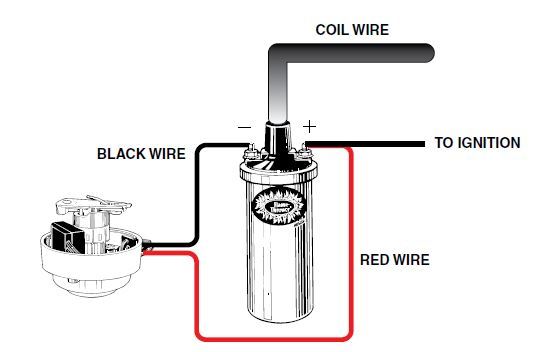
- Attach the black Ignitor wire to the negative coil terminal. (See Figure A)
- Attach the red Ignitor wire to the positive coil terminal. (See Figure A)
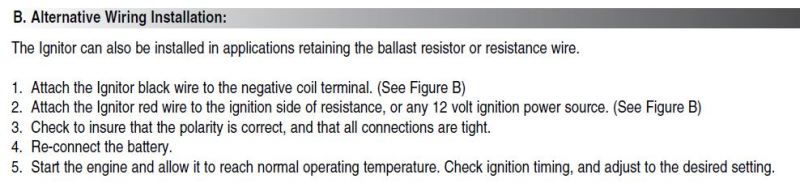
Zray I am sincerely trying to help you. People have done this installation wrong hundreds even thousands of times. The instructions Pertronix supplies are not very good. Even Pertronix admits that. Lots of folks make the same mistake. More importantly, I am trying to keep people from getting bad information that could result in damage to their car. You missed this part of the instructions immediately above the diagram:
Many vehicles came equipped with ballast resistor or resistance wire. To achieve optimum performance from the Ignitor ignition
system, we recommend the removal of these components.
• To remove a ballast resistor, (normally white ceramic blocks 3 to 4 inches long), disconnect all wires on both ends of the ballast
resistor. Remove the resistor from the vehicle and splice the disconnected wires together at a single point.
• To remove a resistance wire, trace the coil power wire, which was previously connected to the positive coil terminal, back to the fuse
block. Bypass this wire with a 12-gauge copper stranded wire.
AFTER you remove the resistor then you can wire it like this:
This is what you have been doing when you add the jumper to bypass the resistance wire. It will work, in that the Pertronix is getting 12+ volts, but it also feeds 12 volts to a 6 volt rated coil and that makes the coil run hot and pulls more current through the switch than it was designed to handle.
Which is why they also show the alternative wiring method which happens to be applicable to Ford products that use a resistance wire.
This is just wrong: “In every wiring diagram that Pertonix supplies, the red wire is connected to the coil + terminal as well as to the ignition switch.” Look at the instructions and see the following diagram from the instructions you just posted.

More instructions from Pertronix:

I am sure that you think I am just some guy arguing with you on the internet, but as it turns out i have been teaching people about 12 volt electronics for more than 35 years.
Perhaps you are a Mobile Electronics Certification Program (MECP) certificate holder https://mecp.com/. I helped create the program, and contributed to writing the training materials and exams.
If you have bought the best selling automotive electronics book Automotive Wiring and Electrical Systems https://www.amazon.com/Automotive-Wiring-Electrical-Systems-Workbench/dp/1932494871/ref=pd_bxgy_14_img_2?_encoding=UTF8&pd_rd_i=1932494871&pd_rd_r=C52F2593XZEQ3H0ZBBYC&pd_rd_w=ZdvQV&pd_rd_wg=YVEfe&psc=1&refRID=C52F2593XZEQ3H0ZBBYCI helped write it and you can find my name in the credits. I supply the author Tony Candela with fuse holders and wire products today.
I also spent over 30 years in my career in 12 volt electronics selling about $30 million a year in wiring products as a Managing Director at Rockford Corp (Rockford Fosgate, Lightning Audio, MB Quart, Q-Logic, etc) I have done training for Alpine, Kenwood, JBL, Polk and several other companies. I have developed products that went into production vehicles for Ford, Chrysler, Mazda, Nissan, and Honda.
With regard to the Pertronix Ignitor product I interviewed the engineers at Pertronix for a magazine article and following that interview wrote articles about how they wanted the product to be installed. Much of the misunderstanding of the product comes from its history. Initially it was not targeted towards consumers. The idea that a consumer would spend $100 to replace a set of $2 points was considered insane. The market as originally envisioned by Pertronix was fleet vehicles, specifically trucks. Those trucks got a new set of points about once a month, and the savings in tune up cost, fuel savings and spark plug life was easy to quantify. The instructions that they still use date back to those trucks. In particular the idea of a resistor wire was not something they encountered in those vehicles. They were very happy to try to get the correct way to do this out there. Following publication they asked me to share the information with other Ford groups. I am not sharing my opinions, rather the best information that the manufacturer offers. I don’t work for them, and we don’t even accept advertising here, so there is no commercial connection involved.
My initial post of how to easily remove the resistance wire from the circuit by installing a jumper wire at both ends still stands.
It’s the easiest way to get 12v to the ignitor and doesn’t damage any other parts, not the ignition switch, not the factory tach, etc. yes there are other ways to achieve the same results, however the method I posted is the easiest.
Regards
Z
PS. I’m not just “some guy” on the internet who likes to argue either. I’ve been building Ford engines since I was 10 years old, 56 year ago. I know what works, and what will damage an electrical system. When I have a car that’s been damaged by my work, I’ll be sure to admit it.
You do get that Ohms law is not a suggestion. If you reduce resistance, current rises. There is no getting around that. The method you describe potentially increases the current flow above the rating of the parts. If you are okay with doing that then knock yourself out. This stuff is well understood from an electrical engineering standpoint. I am sure that you are terrific guy and probably an excellent engine builder. I think your cross-member is a very cool part. I think you can contribute a lot to the community here. I am not trying to insult you. It is important that people understand the implications of what they chose to do.
thanks for the efforts in trying to educate me. I’m sure we will have many areas of agreement, and a few that can never be resolved. This is one of those that will not be resolved. And in past posts I’ve said as much, that we are going to agree to disagree on this one.
From my point of view, and my practical understanding of electrical circuits, my method of bypassing the resistance wire has zero effect of amount of current passing thru the ignition switch compared to your method. On numerous occasions, I’ve measured current at the ignition switch and there is no change in current flow after the P-1 installation when compared to the current flow before the installation. Your method of running a power wire from the ignition switch to the pertronix is identical in effect as my method of bypassing the resistance wire and had the same effect on current flow thru the switch. You are never going to see it that way. I don’t have a problem with that. It won’t be the first time I’ve led a horse to water but couldn’t make it drink. I’m sure you are feeling the same way.
regards,
Z.
PS the good news is that my crossmembers have no electrical connections.
I don’t use the stock Ford coil in my P-1 conversions. I either use the Pertronix coil, or more frequently, one of the MSD coils.
regards,
Z
Those are a great choice, if you are bypassing the resistor wire one would want to use the 40501 black 40511 in chrome or the 40611 epoxy filled. I am not sure that our cars require the epoxy fill. They are all 3 ohm coils and still output 40K volts. If you are leaving the resistor wire in place the 1.5 ohm coils are a good choice the 40001 in chrome, the 40011 in black, or the 40111 in black epoxy filled. Steer away from the .6 ohm and .32 ohm coils unless you are using a relay to provide the power. The coils are a bit smaller n diameter than stock so you might want to pick up a new bracket but the stock one can be made to work with a little modification.
Zray, using the Pertronix Flamethrower three ohm coils listed above are perfect together and won’t produce any problems with the switch or the tach when the resistance wire is bypassed. I am guessing that this is what you have been installing all these years. Many of the folks on this board are interested in retaining a stock appearance so they stick with the stock yellow top coil.
A black Flamethrower with a little John Deere yellow paint on top looks pretty close to stock. There are also stickers available for the coil to complete the substitution.