1970 base cougar convertable
Would anyone have the pin out description for the printed circuit connector on the instrument panel???
Thanks
1970 base cougar convertable
Would anyone have the pin out description for the printed circuit connector on the instrument panel???
Thanks
The wires from that connector go lots of places on a multi-page schematic. I’d be happy to look up what line you are looking for. Or you can get a schematic for free here:
Thanks Calicut. What I’m looking for is what does each pin correspond to in the instrument cluster.
For example which pin for dash lights. Which pin for signal indicator. Which pin for battery power. Etc.
There are 7 pins on one side numbered 3 to 9.
There are 6 pins on the other side numbered 10 11. 13 14. And 16 17.
Thanks
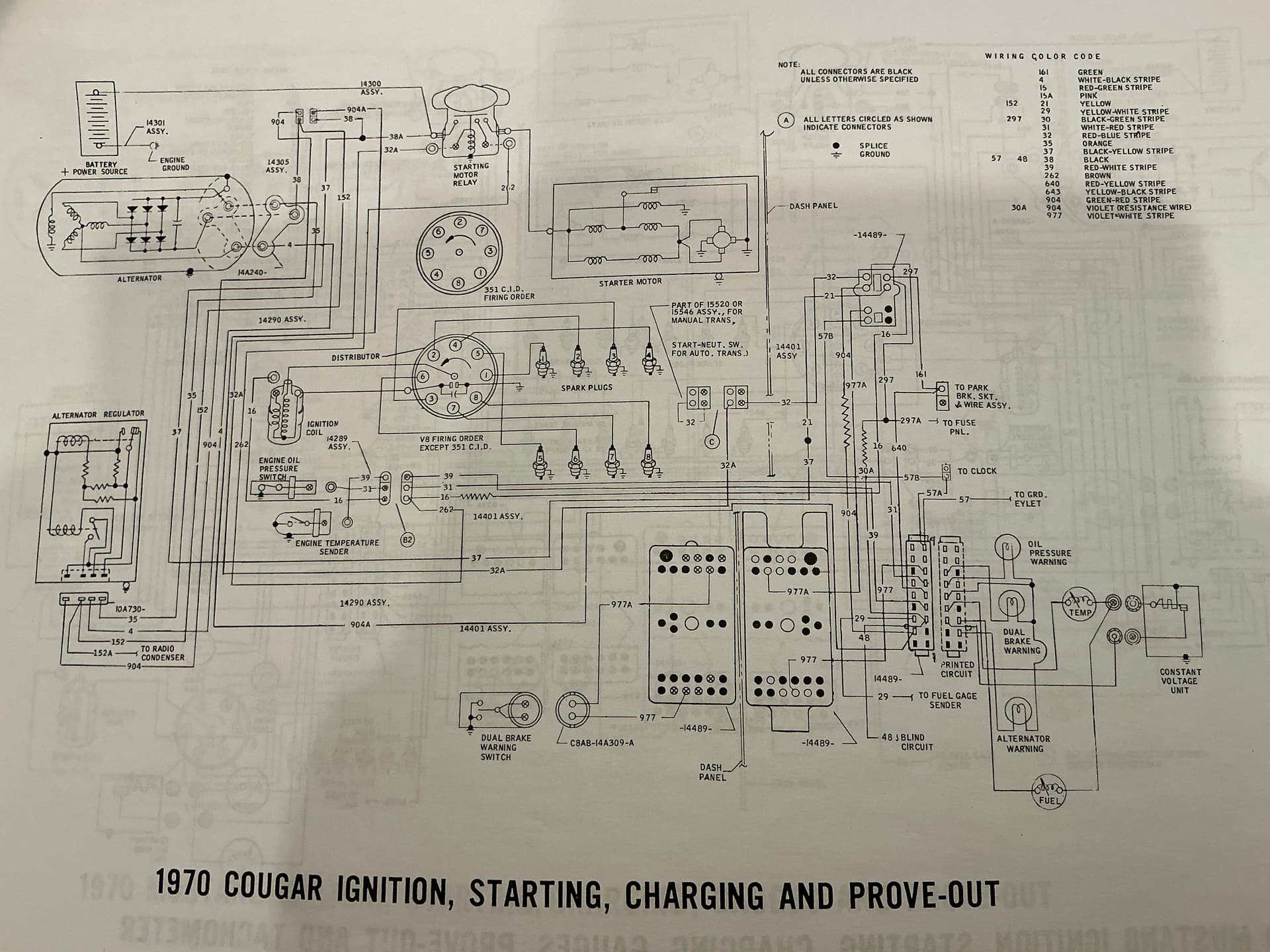
On a standard Cougar it looks like:
1 - high beam indicator
2 - left turn signal indicator
3 - power to instrument voltage regulator
4 - temp gauge (also shown for right turn signal indicator)
5 - 12V to warning lights
6 - oil pressure warning light
7 - brake warning light
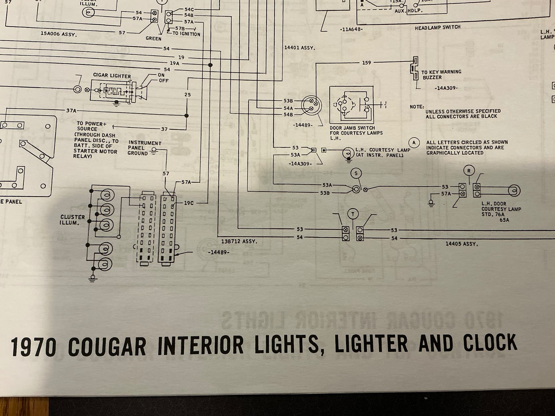
10,11 - cluster lights
16 - fuel gauge
17 - alternator warning light
18 - ground
I must not be reading something right for pin 4 with double use? Maybe Midlife can straighten me out.
Thanks again.
Your pin numbering seems to be different than mine.
My used pins number 3 to 9 on one side an 10-11, 13-14, 16-17 on the other side
Thanks again Calicut!!!
That might help me out a lot.
This is what I have…
| Dash Cluster pin 3 | black
Violet | 484
30 | CVR input power |
|----|----|----|----|
| Dash Cluster Pin 4 | red/white | 39 | temperature sending unit |
| Dash Cluster pin 5 | red/yellow | 640 | coil run signal |
| Dash Cluster pin 6 | white/red | 31 | oil pressure sending unit |
| Dash Cluster pin 7 | purple | 977 | dual brake warning switch |
| Dash Cluster pin 8 | blue/red | 19C | dash lights |
| Dash Cluster pin 9 | black | 57 | Ground |
| Dash Cluster pin 10 | green/black | 34 | high beam |
| Dash Cluster pin 11 | white/blue | 49 | RH turn signal |
| Dash Cluster pin 13 | green/white | 50 | LH turn signal |
| Dash Cluster pin 14 | green/red | 162 | parking brake signal |
| Dash Cluster Pin 16 | yellow/white | 29 | fuel sending unit |
| Dash Cluster pin 17 | green/red
violet | | alternator indicator lamp |
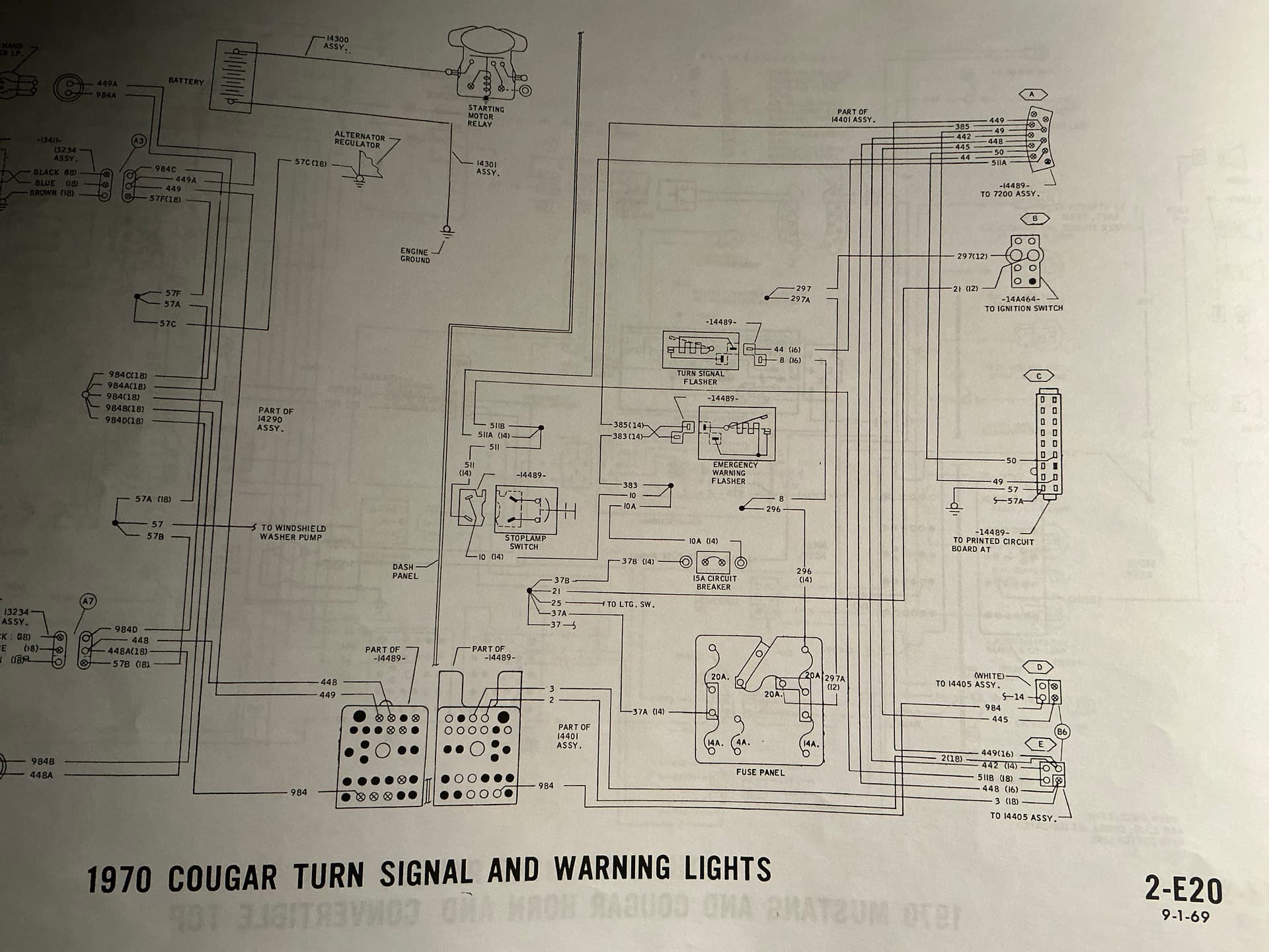
Well, I’m not helping much. Schematic shows turn signal indicator wires 49 and 50 on pins 2 and 4, but that can’t be right. I’d go with Midlife’s pinout.
Get out your meter and test. It’s the only way to know for certain how the car was wired. Keep the smoke where it belongs
Thanks so much. I think midlife’s description is exactly what I need.
From my continuity testing it seems to coincide with midlife’s.
Thanks a bunch everyone!!!
Matching the old connectors to the new AAW wiring harness has been a task I would say.
![]()
![]()
One circuit left to go after the instrument panel.
The courtesy and map lights!!!
Sure glad I ran into y’all. I’m a mustang guy. First cougar I’ve tackled. Learning lots.
Thanks again!!!
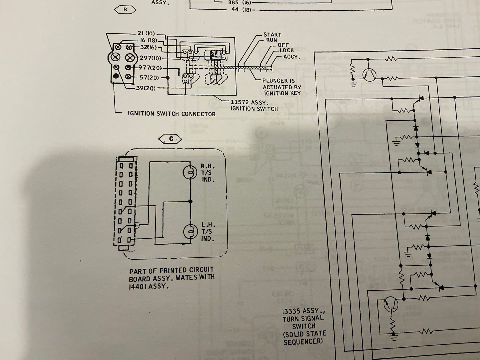
Midlife, do you happen to have the equivalent pinout for the XR7? I am going to spend some time figuring out what is labeled wrong on the factory schematic. I suspect they simply have the connector orientation shown wrong.
1970 XR7:
| Dash Cluster pin 1 | green/black | 34 | high beam |
|---|---|---|---|
| Dash Cluster pin 2 | white/blue | 49 | RH turn signal |
| Dash Cluster pin 4 | green/white | 50 | LH turn signal |
| Dash Cluster pin 5 | red | 655 | ammeter |
| Dash Cluster pin 6 | yellow | 654 | ammeter |
| Dash Cluster pin 7 | yellow/black | 215 | low fuel signal |
| Dash Cluster pin 8 | green/red | 162 | parking brake signal |
| Dash Cluster Pin 9 | yellow/white | 29 | fuel sending unit |
| Dash Cluster pin 10 | red/yellow | 640 | coil run signal |
| Dash Cluster pin 11 | violet | 520 | seat belt signal |
| Dash Cluster pin 12 | black | ||
| Violet | 484 | ||
| 30 | CVR input power | ||
| Dash Cluster Pin 13 | red/white | 39 | temperature sending unit |
| Dash Cluster pin 14 | black/violet | 127 | door ajar signal |
| Dash Cluster pin 15 | white/red | 31 | oil pressure sending unit |
| Dash Cluster pin 16 | purple | 977 | dual brake warning switch |
| Dash Cluster pin 17 | blue/red | 19C | dash lights |
| Dash Cluster pin 18 | black | 57 | Ground |
I’m amazed and thankful of your knowledge with these cars!!!
Where do you find all this info.
thanks for sharing!!!
Thank you Midlife! Your pinouts agreed with the schematics exactly once I finally figured out which schematics are for base, and which are for XR7! I have been using the wrong ones for years, which didn’t mess me up too bad until we got to this instrument panel PC connector which is a completely different pinout for base and XR7 models.
Pawncop, if you still have your original harness, Midlife can make it like new again. Then you end up with the documented factory configuration, and everything plugs right in as it did when new. Just for future reference.
Original harness was burnt up in a few places. Owner said he saw smoke coming from under dash. (Good indication)
Without knowing the harness could be refurbished I installed a AAW harness and used the connectors off the old harness.
I got the instrument panel up and running except the oil light. I believe the oil sensor supplies the oil light a ground on pin 6 but the power for the oil light comes from pin 5 ??? I have nothing on pin 5 as the AAW harness routes the coil power different.
When I apply power to pin 5 my oil light comes on. Hope it goes out once I start it. ![]()
![]()
I definitely found out I took the long way around installing the AAW harness.
Live and learn for next one.
Thanks again midlife. You were a lifesaver on that instrument panel!!!
Glad to hear you got it going! Yes, you will need 12V on pin 5 for any of your dash warning lights to work.