Hey folks - what is the best method for installing the filler neck into the fuel tank?
SitRep: New tank, new seal, original filler tube. With the tank installed, the filler neck is not aligned with the seal and I cannot get the neck to slide all the way into the seal.
This seems to be an assembly step where “close” isn’t good enough.
Any tricks or tips from those who have done this before?
I tried a little silicone spray, but will try something a little more slippery. I did drop the tank and was able to coax the filler into the seal and will leave it like that for a day or two. Perhaps that will stretch the seal a bit.
May also try leaving the tank straps off and tilting the tank slightly while a friend gets the filler tube seated. This may help align the filler to the tank opening…
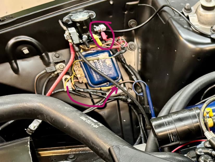
Just a couple comments - you should move the ground strap to the lower rear fastener on the regulator where Ford put it. I think you’ll have grounding issues where it is.
What’s the red wire on the starter side of the solenoid?
As long as everything (including voltage regulator) is well grounded to clean metal on the fender apron, it shouldn’t make much difference where on the apron you ground the cable - as long as it’s not too far from the voltage regulator.
The red wire is likely the direct feed to coil positive. The resistor wire in series with coil gets bypassed when starter is engaged to get hotter spark for easier starting.
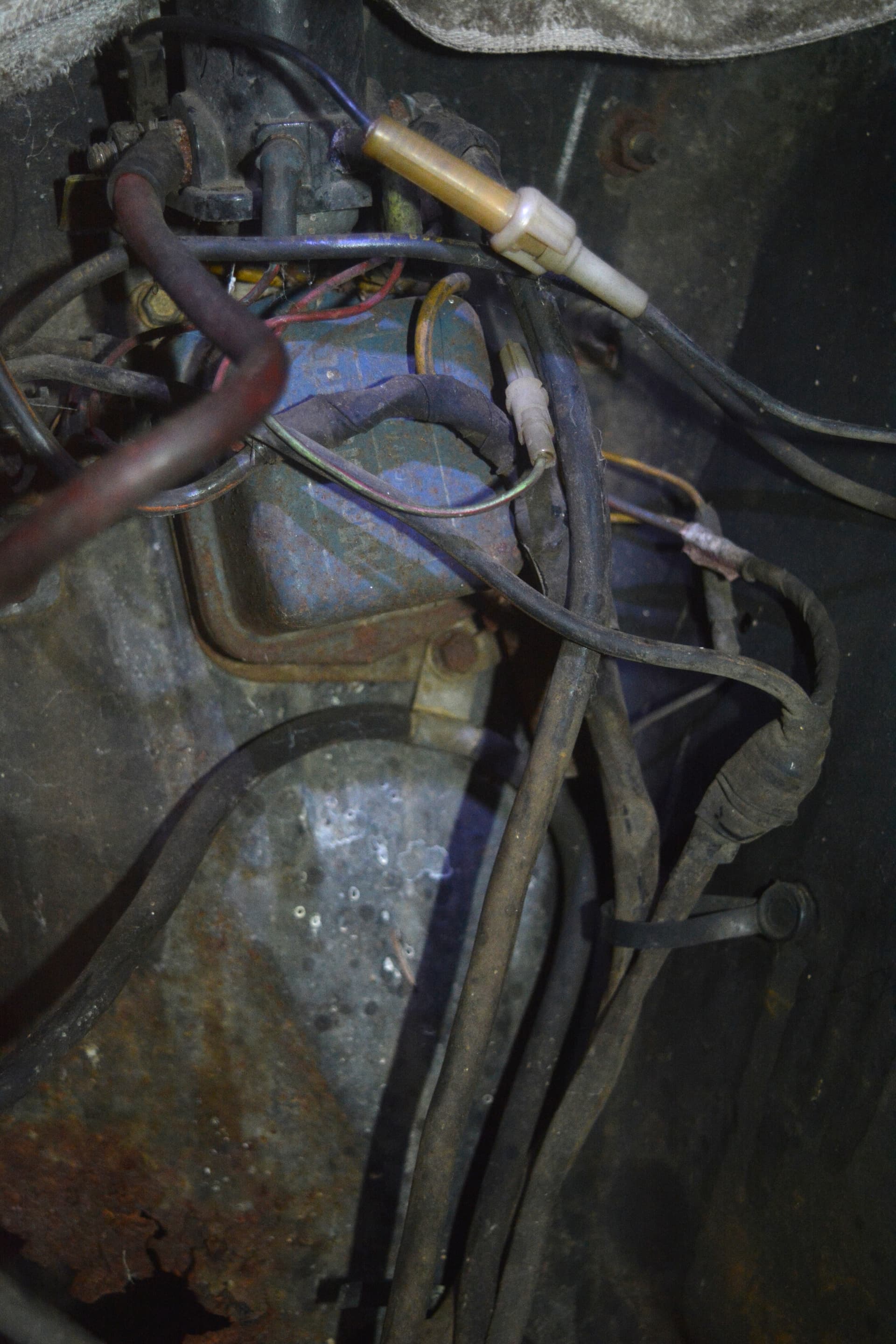
I know this picture is dark and the car was a mess when I took this picture. But this is the 1971 XR-7 I had. Note the red wire (Prove out circuit) is on the starter side of the solenoid and the ground tab on the negative cable is mounted to the lower corner of the voltage regulator. I’m looking for the picture I took when it was done. When I do find it I’ll add it here.
Oh, if your good with whare you have the ground lug, leave it. Only a few woud know and fewer will care.
Coil power during start actually does also connect to the same place inside the solenoid (through its own contact) via the yellow push-on elbow terminal (brown wire 262 on the 70 schematic). And then there is a second wire for cars with low fuel prove out that connects directly to the starter post (red wire 366 on the 70 schematic).
When you think about it, if the starter post got grounded out by the starter, the low fuel light wouldn’t light during cranking, and the solenoid would burn up from dissipating over 1000W assuming it has 11V or so on the battery post while cranking. The starter post of the solenoid actually has about 10VDC on it while cranking on my car.
The negative battery cable is not grounded to the apron, that’s just a retainer. The other end of the battery ground cable is fastened to the block on the front lug underneath the alternator.
Yes, the red/black wire on the starter side of the solenoid is circuit 366 - which is for low fuel indication.
I’m running an aftermarket PMGR starter, so there is battery voltage to the starter motor at all times. On the output side of the Ford solenoid is a 10 gauge wire that runs to the starter motor solenoid. For some reason the starter manufacturer advises against running a single power feed to the starter and bridging the positive starter power feed to the starter solenoid post.
I’ll move the negative battery strap to the bottom of the voltage regulator as pictured above. It’s no trouble to move. Thank you for posting this picture - our car has been apart since 2017 and I’d forgotten where things originally went…
The ground strap should actually ground to the fender apron on its way from the engine block to the negative battery terminal. The original had the insulation stripped under the strap as shown in Badcatt’s picture.
My tilt column isn’t holding position. Was rebuilt a while ago by a reputable shop - but mild pressure is causing the wheel to drop which probably isn’t safe to drive.
The rebuild shop sent me an NOS pawl as a make good. The pawl is engaging the lock pin evenly and properly. The pawl, spring, c-shaped release lever, lever clips are installed per the shop manual.
Not sure why it won’t hold. One thing that isn’t clear is the function of the tiny white plunger and spring under the release lever. It seems to depress properly when the turn signal lever is pressed forward. Could this plunger/spring be part of the problem?
I do not wish to remove the entire column again and send it off for a second and very costly rebuild.
The release pawl has a 1" compression spring that keeps the pawl engaged with the lock pin. I shimmed it with two washers to increase spring pressure. It takes a little more effort to push the turn signal stalk to adjust the column, but it’s a trade-off I’m happy to make.
The wire release bail was slightly bent out of shape. Gently bent it back correctly
Column seems to be holding securely now.
If any forum members are having the same problem with their tilt column, happy to share what worked on mine.