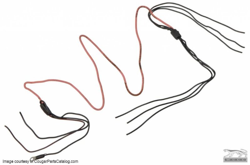
I’m rewiring my 67 and I can’t figure out the purpose of the pink resistor wire in the harness near the tail lamps. I will be using LED bulbs and wondered if lower voltage may mess with the LED’s. The wire is marked not to splice it. Were maybe the tail lamps too bright and Ford put it in to dim them a bit? (Just a wild guess). Thanks for any thoughts.
There should not be a resistor wire in the tail lamp harness. Let’s see a photo - sounds like a creative owner perhaps? (I was mistaken - read on!)
No, there is a resistor wire in the tails of some Cougars for the brake lights. By not splicing it, Ford meant that it cannot be soldered. Resistor wires can be butt-crimped easily enough. If the strands are too small and not enough, add an extra bit of normal wire to the butt crimp to give the crimp enough strength and heat-shrink the pigtail of the extra normal wire so it doesn’t short out somewhere.
Thanks guys, it is in the tail lamp circuit, all 6 and I have removed all the sequential stuff because it’s more of a race car but still licensed. I’m wiring it up like a Mustang but using all the rear lights and this resistor wires’ got me baffled. What would happen if I replaced it with a piece of wire? I can’t figure out why it was installed at the factory. The way it’s set up it would make the tail lights dimmer than normal but not effect the brake or signal lights.
It’s strange to me, but I’ve not studied the circuitry in detail enough to determine why it is there.
Three lamps per side is a lot of wattage for the typical 18 gauge wires, though. Most of the Cougar wires for the tails are 16 gauge…
There is no resistor wire in the circuit of these cars. Let’s see a picture. (I still didn’t bother to look at a schematic)
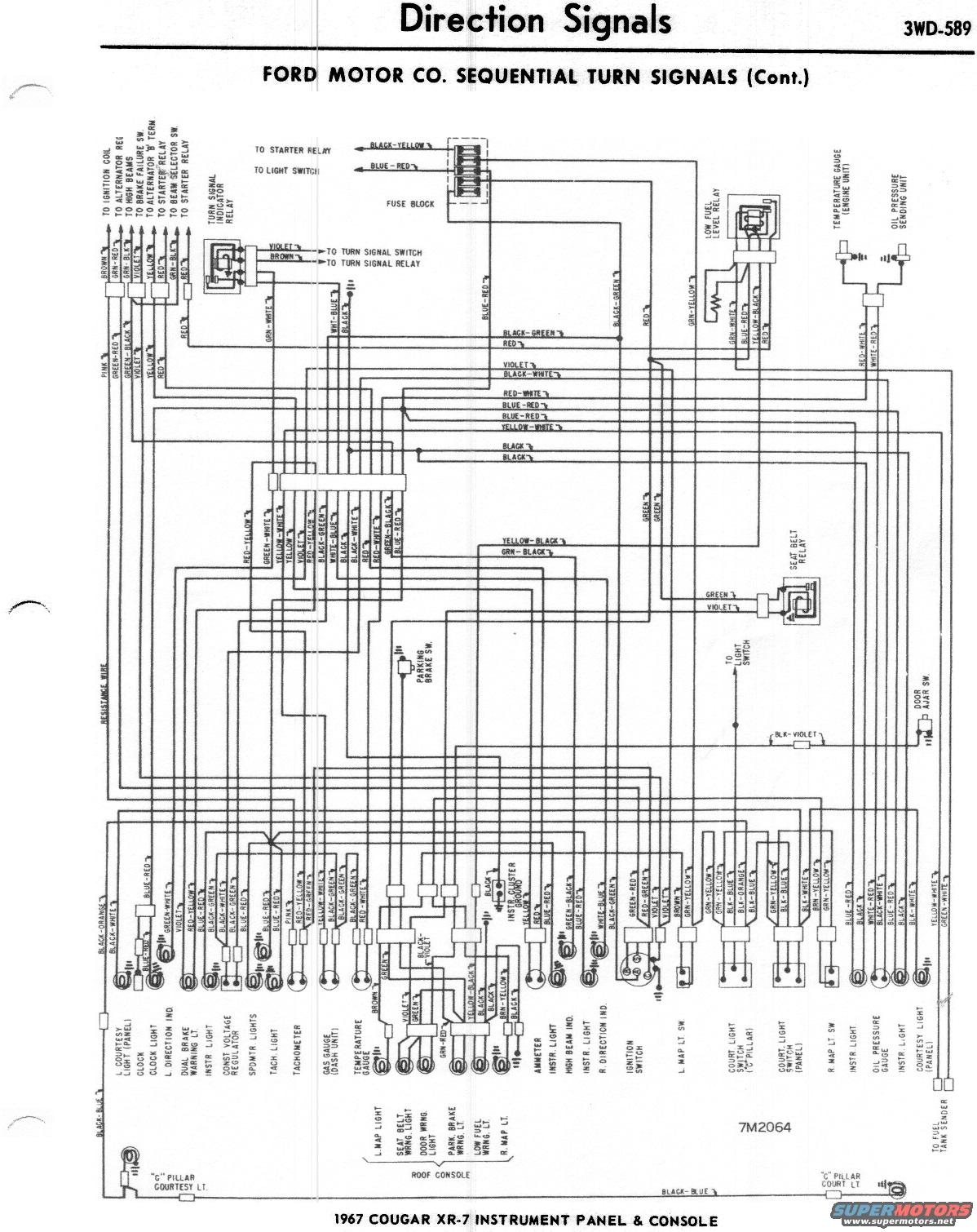
The schematic diagram does show a resistance wire in the Low Fuel circuit - I am not seeing any in the tail lamp wiring.
Royce, I’m not sure if I got the whole diagram on my screen but I don’t see any tail light wiring at all.
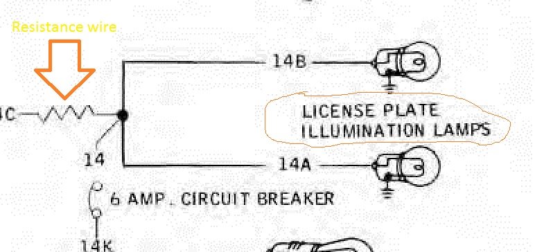
OK found it - there is a resistor wire in series with the two license plate lamps. (Actually it’s in series with the six tail lamps. Power is uninterrupted to the license lamps.)
Thanks Royce, the first time I’ve seen that schematic. There is a circuit breaker and then the wire continues to the license lights and then to the resistor, then on to the tail lamps, lowering voltage to all 6 tail lamp filaments. Exactly what I am seeing on my car. the license lights are on the 12V side. Now the big question. Why did they do it? It’s crazy.
It’s not crazy if it works. I first learned of this by researching this thread. I’ve owned something like 60 67 - 68 Cougars since 1973 an never once had a problem with this. Why would I care if there is a reason? It’s a non issue, a trivia question.
I’m building a new rear harness for my Cougar without all the sequential stuff and was going to use the LED/plasma bulbs and not sure if I should leave it in the new harness or not before I tape it all together… I’ll admit there is a little curiosity in me as a gearhead though.
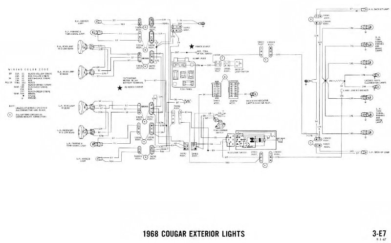
The same six bulbs are present in two wiring diagrams on my 1968 electrical manual: Exterior Lamp Circuit and Sequential Turn Signals. The exterior lamp circuit shows them wired with the resistance wire. The Sequential Turn Signal Circuit does not. Unless I’m reading the diagrams incorrectly, I believe the resistance wire is there so the bulbs glow at a lower level while the Exterior Lamp Circuit is active. This allows the turn signal and brake switch circuit, which does not have a resistance wire, to activate the lights with a separate, higher voltage and thus glow more brightly. Without the resistance wire on the exterior lamp circuit you would have to have two bulbs in each position to accomplish the same thing.
The wiring diagram that I posted shows the resistance wire in series with the ground for the license lamps only. It has no effect on the tail lamps or turn signals.
The tail lamp bulbs have two filaments, one is for the turn signals and the other for the tail lamps. The resistance wire has zero effect on any of that.
Royce give that another look. You can see the ground symbol at each lamp. It looks like the only taillamps not powered by that wire are the license plate lamps.
Hmmm…I wonder since most cars of that era used only a single license plate bulb, and the Cougar used two, that having two bulbs at full voltage would be quite bright, especially located between the left and right sequential bulb sets. One could be confused seeing white lights (at night) at the interior end of each tail lamp assembly and assume that was a backup light. By lowering the voltage to the license plate lamps, illumination was still possible with the same lumens as having one bulb, but with a more distributed light source. With a lower intensity, confusion with backup lights (at night) would be lessened.
What do y’all think?
Bill I see what you mean, the license lamps are the only ones getting 12 volts. Apparently the rest of the lamps drew too much current without the resistor which is understandable since the Mustang only had two tail lamp bulbs.
The resistor would share the load with the lamps, the load would be the same just lowering voltage to bulbs making them dimmer. Which is strange because the 1157 bulbs are already made with a dimmer filament for the tail lights vs. the brake/turn lights.
Well, it appears that I had it backwards: the license plate lamps get full voltage but the running lamps side of things get lower voltage. If the intent was to fully illuminate those running lamps, why not simply use a smaller (numerical) gauge wire to handle the extra current? Since Ford decided to restrict the current, it has the same effect of lowering the brightness of that line for the 3 bulbs on each side. That has to be the only reasonable explanation, as a resistor wire is more expensive than going to a different gauge wire.