On a 68 I installed LED taillights and due to low current I need to replace the flasher but can’t find where it is located?
What is not flashing?
The turn signal lights on the dash are not flashing.
I wrote this for Legendary Cougar Magazine. There are probably a few things that need to be updated. BB
Light up the night: Modern lighting for the Classic Cougar.
Over the years the lighting systems on our Classic Cougars have become more of a liability than a source of pride… In 1967 the Cougar was the state of the art when it came to exterior lighting. Fist we take a look back, and then learn how to apply current state of the art technology to make your Cougar light up the night once more.
America was in love with the automobile in 1964, and the designers in Dearborn were going all out to dazzle and amaze the receptive public. The newly designed Thunderbird had tail lights that ran almost unbroken from side to side. What was even more exciting is that the engineers had developed a new sequencer that would make the three tail lights on each side flash in sequence in the direction of the turn. The big bird would have the flashiest tail in town once a few legal hurtles could be cleared, postponing introduction until 1965.
When the new '65 model Thunderbird hit the streets the sequential lights were a hit. Thunderbird drivers had to get used to being followed around town by other drivers anxious to see the awesome display. The reaction was so overwhelming that some owners even complained to dealers about the number of unwelcome followers.
Car Life Magazine chalked it up to “Gadgets and Gimmicks to suit the American taste”. Whatever the scribes might call it, the designers working to finalize the new Cougar were after anything that would make the car unique and different from the Mustang. A staff member from the Electrical Engineering department that brought the idea to Lincoln Mercury Advanced Design Studio Manger John Aiken. Aiken developed a mock-up and incorporated it into the clay model. Not long afterwards Gene Bordinat, Vice President of Design for the Mercury Division, green lighted the new design and the Cougar would become the second vehicle on the market with sequential tail lights.
Had more time passed, the Cougar might have been missing it’s sequential feature. Thunderbird owners started having problems. Among other issues, the dash mounted turn signal indicators were not flashing even though the exterior signals were working properly. As the warranty claims mounted, the engineers were scrambling to find a fix. The Cougar would not be immune from these problems. There were many running changes to the design.
The original system was entirely electro-mechanical. A motor would turn a group of cams that closed a series of leaf switches. Relays would separate the brake light, emergency flasher and turn signal light functions. All of those components are very robust, as evidenced by the number of original systems that still work, A least to some degree, nearly 50 years later.
In 1969 a new electronic version would become the standard. At least for a while. As the system aged the brake lights were becoming dim, so the system reverted back to a conventional style relay to fix the problem. If this were not enough, starting in 1970 the front side marker lights would also serve as turn indicators. Finally, in 1971 the system was pretty well sorted out until being discontinued in 1974.
Advances in electronics have impacted every aspect of our lives. Finally modern technology can be applied to our Cougars. LED lighting is brighter, more durable, and far more efficient than conventional incandescent bulbs. However, those LEDs do not work on the same principals as their old technology ancestors. Converting to LEDs may require upgrading of the sequencer, turn signal flasher relay, and even the use of side market light circuit adapters to make it all work.
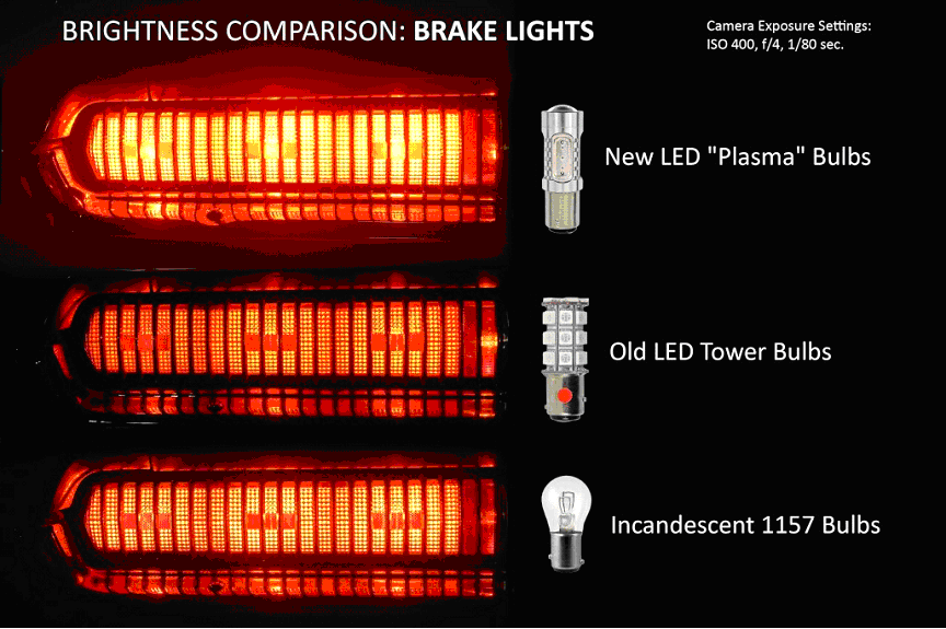
The good news is that Cougars Unlimited and West Coast Classic Cougar have risen to the challenge. West Coast Classic Cougar, after years of searching, located a new Plasma LED that provides a level of brightness that the old incandescent bulbs and even the early tower style LED bulbs could never achieve. Cougars Unlimited developed entirely new sequencers, turn signal indicator flashers, and side marker adaptors.
The bad news is that there are lots of “buts” involved in doing anything less than a complete conversion. For example, you can change out the rear lamps in the '67 and '68 and they will work and be super bright, BUT, the dash turn signal indicators will not flash even though the rest of the system is working. Granted, the dash indicators seldom worked even with the stock system.
For most Cougar owners, this should be considered an all or nothing conversion: LED bulbs, Sequencer, Turn Signal indicator flasher, and side marker light adapters as required. Once you see how good the new LEDs look you are going to want to do the entire car anyway. For the first time you can feel confident that other drivers will see your turn signals and brake lights.
In this article we are going to upgrade the rear brake and turn signals, the back up lights, the front turn signals and parking lights, the front side marker lights, the sequencer and the turn signal indicator flasher on a '68 Cougar XR-7. If you are working on a '70 and up you will also need side marker light adapters.
Upgrading to LEDs is actually one of the easiest projects you can do, the tricky part is being sure that you have the right parts. The original systems were problematic and the regulations covering exterior lighting changed frequently. This produced a whole series of slightly different systems. Today this means that depending on the year of your Cougar the parts required can be very different. The following chart shows what you will need to upgrade your car.
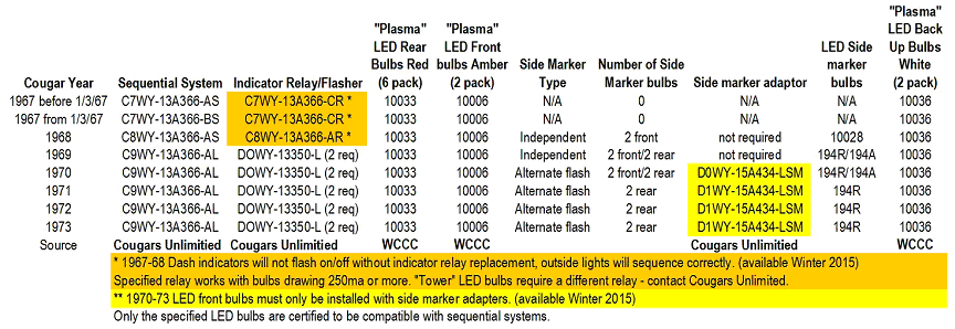
This article is based on the ''68 Cougar. The '67 is very close but depending on build date the plugs for the sequencer will be different. The '69 and up all use the same sequencer. Removing the lamps will vary by year so refer to the factory service manual. Sorry '71 and up this is a lot more difficult on your cars.
As always, Refer to the factory service manual for specifics for your Cougar. Although this is an easy project, if you are not familiar with basic mechanical procedures you may wish to have this done by a professional. Always disconnect the negative battery terminal before starting any electrical project and wear proper protective gear, in particular eye wear.
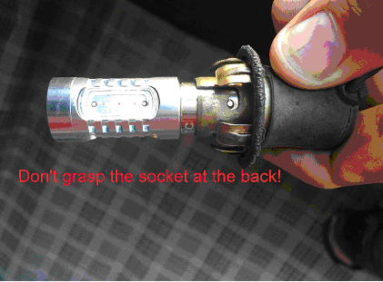
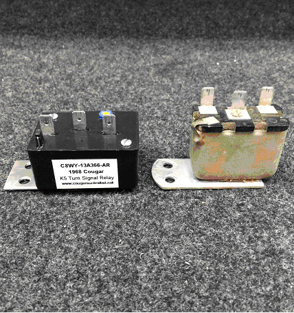
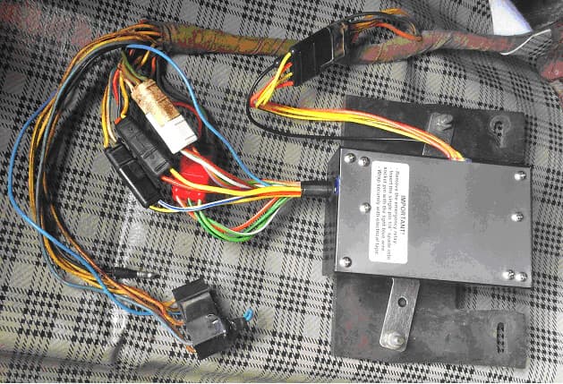
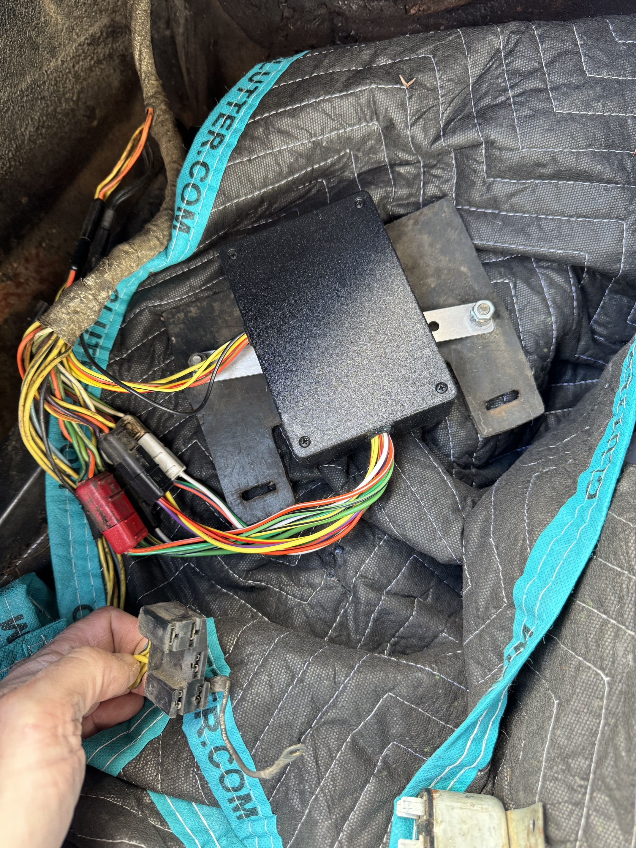
- Start by disconnecting the negative battery cable. DO NOT reconnect this cable until the installation is completed. The sequencer on '67 and '68 Cougars is located in the drop down at the left rear quarter. The emergency flasher relay is also removed. Unplug everything. Remove the relay block and sequencer from the rubber mount.
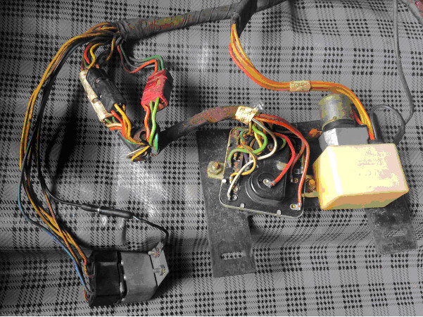
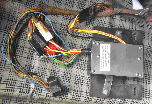
- Mount the new sequencer in the original location using the original nuts and bolts. The plugs are color coded. Plug the single spade connector into the black plastic emergency relay connector in the socket matching the light blue wire. Use electrical tape to secure this wire to the connector.
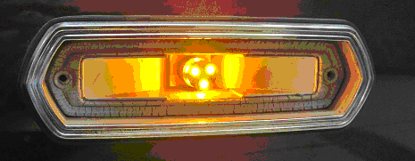
- Remove the six tail light sockets from the reflector assembly. The sockets are a friction fit and pull out. The sockets are grounded by contact with the reflector. This is a good time to use a wire brush or sandpaper to clean the contact surfaces. Remove the old bulbs from the sockets. To remove the bulb, hold the socket by the middle ring. The socket is spring loaded and the back part must be able to move backwards to get the bulbs out. Once the new bulbs are installed replace the sockets in the reflector. Note that the socket and reflector are keyed for alignment.

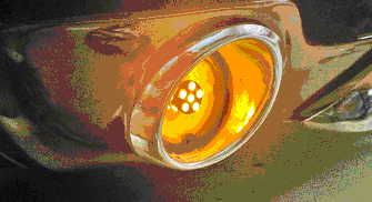
- Front turn signals, side marker lights, and reverse lights are next up. Each lens is held in place by two screws. These sockets are frequently corroded so it is a good idea to shoot a little penetrating oil in first. To remove the bulb you have to push in and turn. Turn signals and side markers have a two pin connector in the base. Temporarily reattach the negative battery cable. Polarity is important so test the installation before putting the lens back on. Replace the lenses.
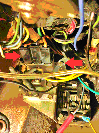
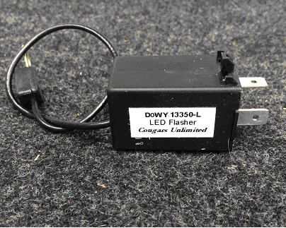
- Disconnect the negative battery cable. The turn signal indicator flasher is located adjacent to the fuse box, attached to the wiper motor bracket. Remove the plug and then the two 1/4" screws. Getting to this is the hardest part of the entire project. you will need to remove the two screws and then attach the new flasher in the same location. Note: this flasher will also work with incandescent bulbs to make your dash indicator lights flash once and for all! This completes the installation.
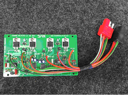
If you are working on a '69 or newer Cougar the sequencer board is installed inside the original protective plastic housing. You will also need two of the replacement turn signal flashers as shown.
Starting in 1970 the front side marker lights are used to signal a turn. The side marker and the front turn signal flash alternately. To accommodate this design requires the use of side marker adapters. These are a plug and play style that require no cutting of wires. You remove the socket from the factory location and plug the adapter in place of the original bulb.
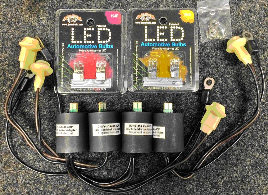
Photo credit to WCCC for tail light picture.
2 Likes
Thanks again to Don.
I just installed this relay in my 1968 and I am confused as to what to do with the emergency flasher relay plug. It shows here that you are supposed to install a single spade connector into the blue wire socket on the 5 pin; however, this single spade wire did not come with the kit I purchased from WCCC(#26707). I see the picture above with the connector wrapped in electrical tape, but I cannot see what the actual connector looks like in order to just make one for myself. Is it just a single wire looped onto the connector inself? It doesn’t make sense that this would be needed if that is the case. Is it just to close the connection? As is, my signals work and the center light flashes when my emergency flashers are triggered, but I am concerned that leaving that connection alone may leave an open circuit. Does anyone have a picture of the spade connector installed into that blue socket on the 5 pin connector WITHOUT the tape covering it?
It’s a male spade. It’s just like the spade on the relay you just unplugged. Does your box have the wire with no connector?
I can see the the connector wrapped in tape in the picture above, I’m just concerned that #1: I didn’t get the spade connector included with the kit I ordered, #2: I can absolutely make a connector on my own, but I don’t know if it is essentially a jumper that closes the circuit, or if it is a jumper from the blue wire to another connection in the plug. By the looks of it in the picture, it looks to be a simple loop from one side of the spade to the other, which makes no sense. But it’s wrapped in tape in the picture so I can’t see what it is actually doing.
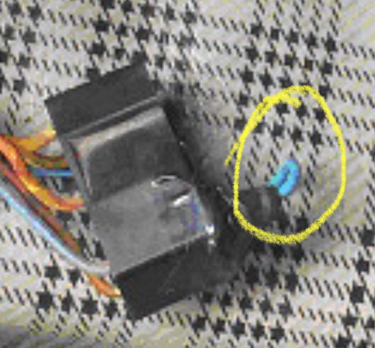
You are over thinking this. look inside the plug. See the female spade connections? You need the corresponding male connector to plug into the female side. The tape is only there to provide a little additional support of the wire so it won’t pull out.
Are you telling us that you have the blue wire with no connector on the end? If so just add the connector and plug it in. If you do not have the blue wire you need to return the unit (assuming they still need that wire).
Mount the new sequencer in the original location using the original nuts and bolts. The plugs are color coded. Plug the single spade connector into the black plastic emergency relay connector in the socket matching the light blue wire. Use electrical tape to secure this wire to the connector.
The only thing that was in the box was the digital conversion box. It did not come with any additional loose wires or connectors. I’m okay with making my own, I just can’t see past the tape in the picture so I don’t know if the little blue wire is just looping to a single connector. I can’t process how or why it would need to do that other than it terminates that connection, but the connection is terminated since it is unplugged anyways. It’s so hard to just describe these things. But if this was supposed to come with a single spade in the box with a blue wire that makes a loop on that same single spade connection, than I am missing that part.
Look at the single blue wire coming out of the sequencer box? See how it goes to the molded black harness plug? It runs under the plug and then the spade connector goes into the black plug. The tape is there to support it. Do you have the single blue wire?
That blue wire has been eliminated on the newer boxes. Justin at WCCC had a call about that and he contacted Vic Yarberry who told him it had been removed and to just unplug the emergency relay.
Well shit, that makes much more sense. Don, or anyone looking over the products at WCCC, I would advise you to update the instructions or at least note that in the product description.
I think I wrote that article maybe in 2014?