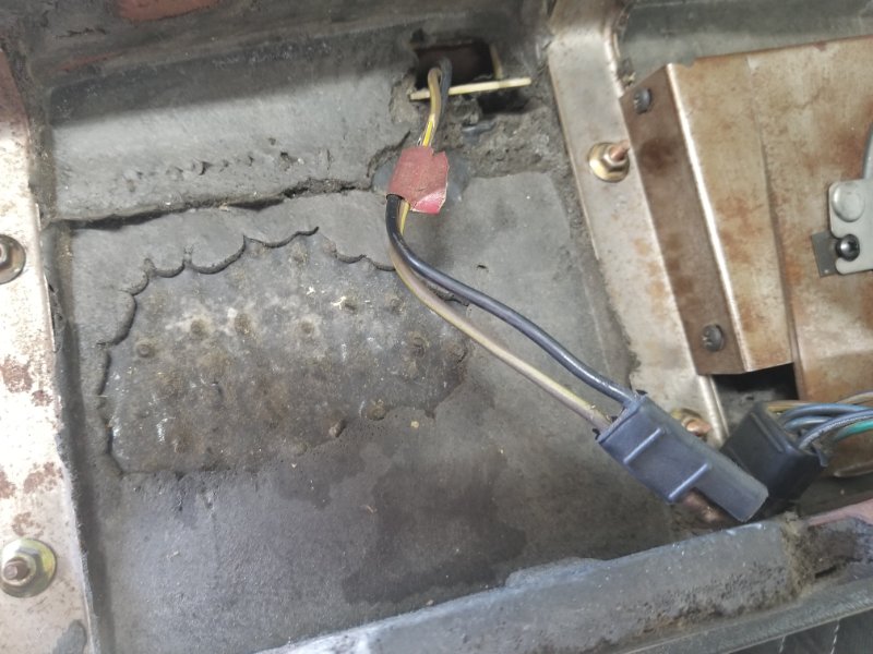
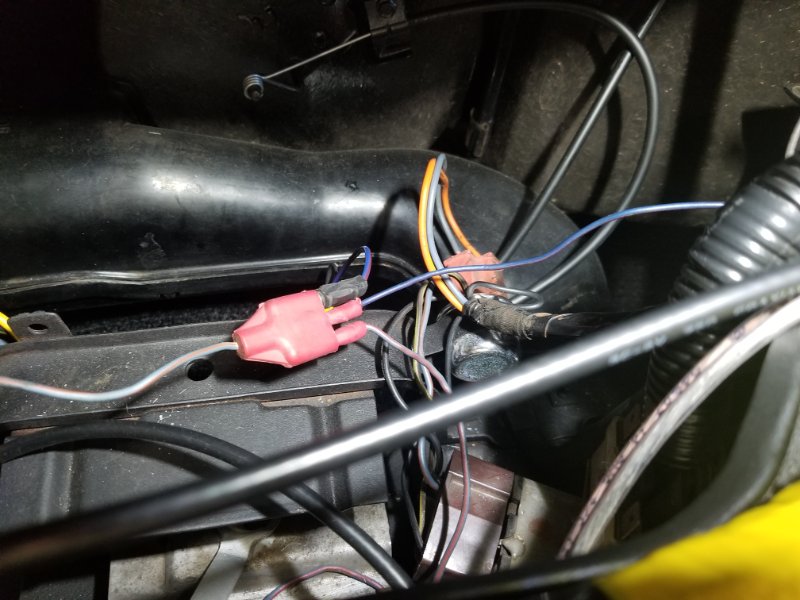
I would appreciate a check on the dash wiring connections for the 70 xr7. Out of the red plug 3 female connector i have clock harness, ashtray light and heater control light. Is this correct? I am thinking no because i can’t find out where the map light harness plugs into. Here are some pictures
Can’t say I remember all of that detail. I labelled all of mine the first time it came apart. A set of wiring circuit diagrams and pictures are available from West Coast Classic Cougars as a free download. There should be enough there to answer your questions. https://secure.cougarpartscatalog.com/19mecocoelsc.html?sessionthemeid=26
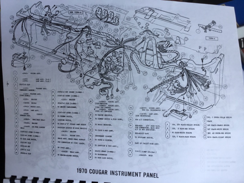
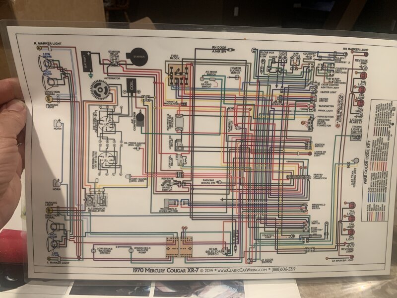
Looking at the 70 schematic, the 3 pin red plug fed by the single blue/red stripe wire goes to clock light, heater control light, and I believe ash tray light. All three are shown as blue/red stripe wires. The clock power and ground comes from a green two pin connector with black and green/yellow stripe wires. Map light and switch gets power and ground from the two pin black connector fed by black and green/yellow stripe wires.
Hi, thank you for the reply. I labeled everything as well but I’m starting to second guess my work because I’m not seeing the plug where the map light plugs into. I have the WCCC drawings but I have trouble seeing them and they don’t show color. My problem is, the gauges and clock don’t work. The back lights work and the amp gauge works but that is it. And the lights are a bit weak. The cluster was rebuilt and I just replaced the IVR but no go.
Craig, thank you. It looks like I do have the wires hooked up right except I can’t find the map light plug. Something must be missing. Do you know where the ground points are for the cluster and clock? Thanks.
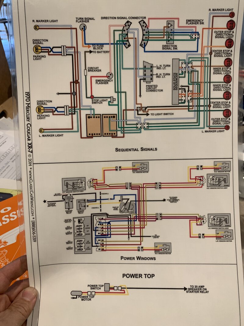
Hmm, see if this 70 XR7 dash diagram helps any. Only ground I see is E over on drivers side. Not sure why the clock connector is shown as three terminal in this diagram, though.
You should have 2 connectors in this area See numbers 42. One with the 2 wires as I recall is the map light and the one with 3 wires is the clock. It may be hiding on the bottom side of your harness. Did you re-tape your harness?
Also check the part number on the clock harness. You need a D0 par number. If it is a C9 you will have problems with it. It has been a few years since I took my dash out of Ginger, but I have done it to many 69 and 70 XR-7s.
This is a better picture of the two connectors for clock and map light I was talking about. But this diagram shows a 3 terminal connector for clock, while the schematic shows a green 2 terminal connector for clock containing both power (green with yellow stripe) and ground (black) and then a single bullet connector for power to the 2 clock lamps (blue with red stripe). But maybe all three got routed through the same 3 terminal connector as the diagram shows? I just don’t remember.
This agrees with the Ford schematic - 2 terminal connector to clock containing power (green with yellow stripe) and ground (black), and then a separate wire with single bullet connector (blue with red stripe) for the clock lights.
Just a note of caution those colored diagrams are not always correct. As you will notice on your 70 XR7 diagram shows the rear side markers are grounded, actually they will continue the circuit to the front side marker as they are part of the turn signal.
The clock harness is the correct one with the D number. I’m still trying to find the map light plug. One thing I did find was that the half moon steering column ignition switch plug was not completely connected. It wasn’t snapped in. Could this be why my gauges don’t work?
I’m not familiar enough with the Cougars, but the map light in 69/70 Mustangs are separate harnesses that plug into the clock harness. They are not reproduced and fairly rare.
I think that you will find that the 69-70 XR7 map light wiring is a part of the under dash harness. The 69-70 XR7 map light does not have an on/off switch on it like the map light used on a 69-70 standard Cougar or a Mustang.
Yes I knew that but you’d be surprised at how many people call me trying to trouble shoot their marker light and don’t know that the marker is part of the turn signal system so they don’t turn the diagram over. The 70 not to bad but the 67/68 diagram has sever mistakes and some systems left out. I use the Ford shop service diagrams, the Osborne diagrams and several engineering diagrams, and they all have mistakes. I think sometimes I create mistakes just trying to find how they work. Thanks for bringing it to my attention.
Randy, I completely unwrapped the harness at all the areas where this map light plug might have been hiding. I’ve concluded that there is not one and there is no indication that anyone before me has messed with this harness. I am at a loss. Perhaps this was assembled with the mustang type extra harness for the map light.