Folks,
Decided to give Holley’s new Sniper EFI a try on our '71 XR7. We need a good source for 12 volts when cranking and running. Holley cautions against coil + wire or solenoid as this source.
Any ideas which ignition switch wire might provide this? I have the wire diagrams but they don’t provide a lot of clarity or close in detail on ignition switch terminals.
This is the same issue as the Pertronix. The best choice is to use a relay that is triggered by the coil wire. The key switch is only about an 8 amp switch. You can use it but if the current draw is very high then you run the risk of burning up the switch. The wire you need is the pink green strip that goes to the tach. If you splice into it before the tach it you will get a full 12 volts. The resistance wire is between the tach and the fire wall.
Constant hot or switched 12V? The FiTech I installed uses a constant hot which I connected to the incoming solenoid side. It’s got an inline fuse between the connection and the ECU. Works fine so far (about 600 miles).
Regarding current draw, the Sniper EFI has a dedicated battery connection for unit power, so the switched 12v wire is not pulling much current, rather just telling the ECU that your cranking and running. However, like your idea. I’ll use that wire as the trigger on a SPDT relay, and use the battery as a clean 12v source and the Sniper EFI switched power wire as my relay normally open output
As a follow up, I ended up tying into wire 904 (green, red stripe) at the pigtail near the voltage regulator. This wire comes off the ignition switch at the same terminal as the coil wire and is energized at both crank and run. I’m using it to trigger a SPDT weatherproof relay that draws power for the COM connection from a dedicated battery feed. Works like a charm.
Thanks Bill B. for recommending use of a relay. This relay minimizes extra current draw from the existing circuit which can sometimes cause unforeseen problems.
Just so you know, circuit 904 is hot when you turn on the switch but before you start the engine.
The only two circuits that are hot only in the Start and Run mode is circuit #16 and circuit #262 (which physically connects with circuit #16). Circuit 16 is fed from the ignition switch, priorto the resistance wire is a full 12 volts, beyond the resistance wire, it will be around 8 to 9 volts. Circuit 262 is fed from the Starter Solenoid’s I post, this circuit will have a full 12 volts when starting and will have 8 to 9 volts when running (backfed from circuit 16). 8 to 9 volts is sufficient to trigger a 12 Volt relay.
I use a wire with a ring terminal and attached it to circuit 262 as a trigger for my relay.
I know I’m a bit late to the thread, but I’ll still add my 2 cents.
I also use the 904 wire but I use it directly with no relay and I tap it exactly how Gyrhead did his. Has worked fine for 4 years on my Pertronics and now with my Holley Sniper setup (~ 6 months). I could see the use of a relay to limit any additional current draw off that circuit and possibly give a “cleaner” voltage.
Jay
Jay, you need to measure the voltage on this circuit with the engine running. It is being fed by the resistor wire and providing you with reduced voltage.
Circuit 262 is fed from the Starter Solenoid’s I post, this circuit will have a full 12 volts when starting and will have 8 to 9 volts when running (backfed from circuit 16). 8 to 9 volts is sufficient to trigger a 12 Volt relay.
Interestingly, the 904 circuit on my '71 Cougar was quite effective at triggering an SPDT relay to power a Holley Sniper system. However on my '70 Torino Cobra - the 904 circuit did NOT have enough power to reliably energize a relay to power my wideband O2 gauge.
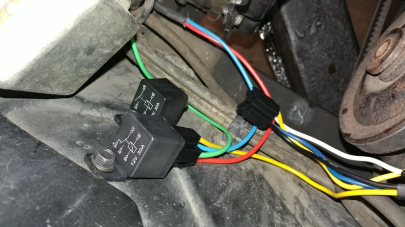
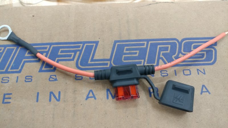
Well here are some pictures of an in-line fuse and switched 12V relay setups. These are in process pics and I’ll neat things up once tested. They’re for the computer that’s going to control my retrofitted 6 speed Automatic transmission. Like suggested, I need a clean and solid 12V / 10A circuit to power the computer but also neutral lockout and back up light bulbs. Separate dedicated circuit for an electric fan and choke power.
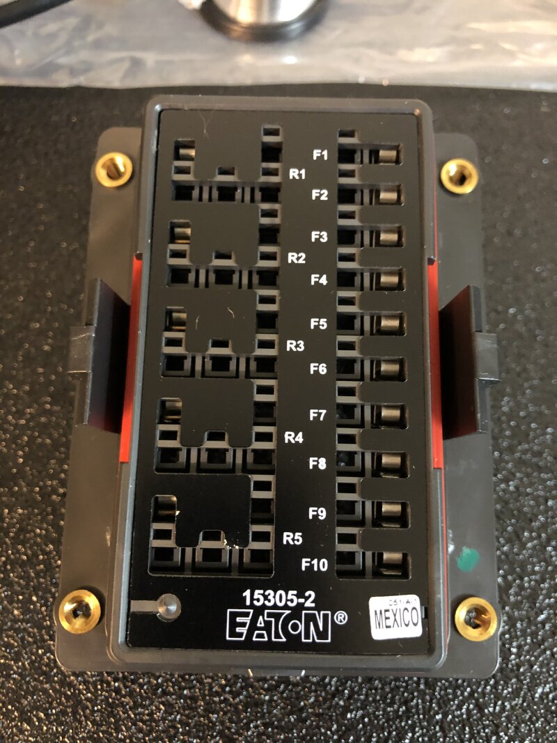
This may be of help to those adding circuits for a clean install. It has two B+ input buss connections that will allow you to wire constant B+ and switched B+ if needed. It houses both the relay and fuses so its pretty easy to keep everything in one place.
No predetermined wiring diagram, you build it to suit your needs which is pretty easy. The B+ is already preinstalled(note the pins visible) Those are going to be what connects to the input studs on the rear of the unit. The great thing is you can wiring it either B+ or accessory + if needed. Ill follow up with how I wire mine when I get to that point.
I do believe there is a prewired unit out there but its not all that cheap.
Bill,
I’ll check into that, but from looking at the schematics I have for the 69 Cougar models, the resistor that is mentioned in this circuit is only in the standard Cougar. When I review the XR7 schematic I do not see the resistor in that circuit (904).
I see wire 38A feeding to wire 37, then through the firewall connecting into wire 21 which is the feed into the ignition switch (B). Ignition output “C” is the 904 wire and that runs back through the firewall and up to the voltage regulator. I see no resistor indication in any of this wiring. Again I’m looking at the XR7 wiring. In the standard cougar wiring, I do see what is mentioned above. On the XR7 schematic the 262 wire ends up feeding the tach via 16A and the coil via 16. Also one other point regarding my setup, I have the upgraded Tach so the tach is not in “series” with the ignition any longer. Also I have the Holley Hyperspark and CD box so the 16 wire is no longer connected to the coil, the coil is fed from the CD box.
I will still make the measurements you suggest just so I can verify my schematic interpretation.
Thx,
Jay
Sometimes when the alternator squeals on Stratton up it is because the battery has lost significant charge while the car is parked. What you can do is use a multi meter to measure current with key off and car not running. It should be less than a half amp. Much more means something is not turning off.
So I did the testing of the 904 wire that I tap at the voltage regulator in my 1969 XR7.
I get 0 volts when ignition is off.
+12 volts when ignition at run (engine not running).
+14 volts when engine is running (alternator doing its thing).