Fascinating - thanks for taking the time to document and post!
- Phillip
Fascinating - thanks for taking the time to document and post!
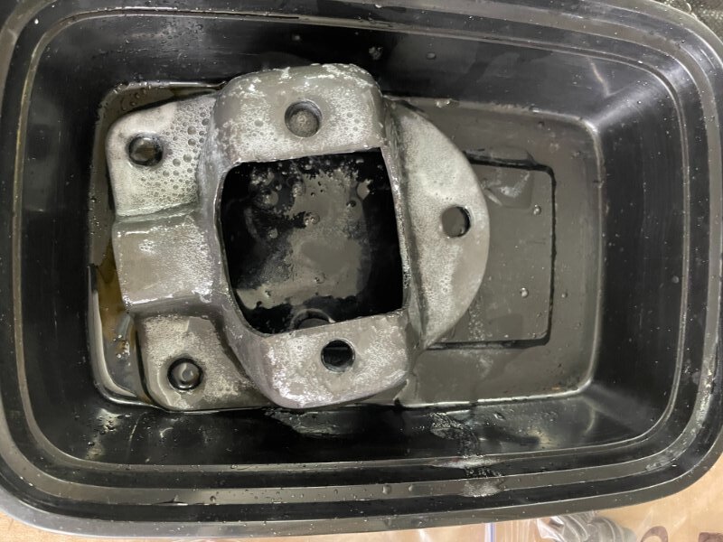
The part will start fizzing once placed in the solution indicating the reaction is taking place. Scott recommends leaving the part in the solution until it stops fizzing however the parts will turn almost black at that point. I use the test pieces as a time gauge to measure time and color to set a standard of when to remove the parts, especially on the larger ones to maintain consistency between pieces.
I found that 4-5 minutes in the solution gave me the finish i was shooting for. Once you have the finish you are looking for remove the part from the solution with the stainless tongs and dip in the clean warm water to rinse. Blow the part dry after rinsing then place in a tray or bowl and soak with WD-40 on all surfaces.
I like to give the parts time to cool then wipe them down with a WD-40 soaked cloth or towel then pack them in bags to await assembly.
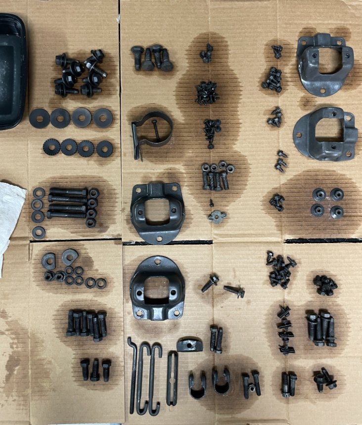
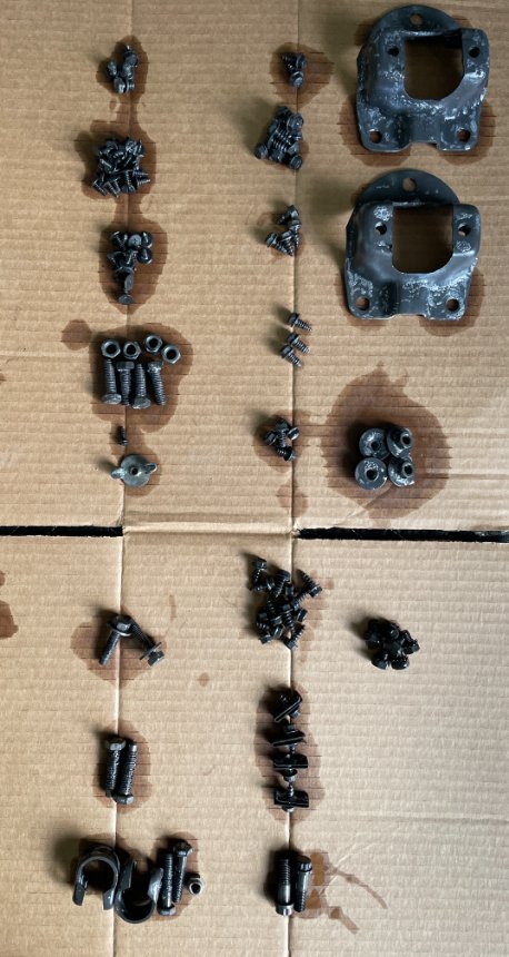
You can probably see that the two shock plates in the top right of the first picture have some white residue which is mineral deposits. My rinse bowl didn’t have enough water on it the first round and when I placed the part in the bowl the minerals settled there. These were test pieces so I wasn’t too concerned but sometimes you can put them back in the solution for a few seconds and it will rinse off. Otherwise you have to blast the part again and start over.
The process will tell you if you did a good job blasting, if there is any rust or if it is a coated bolt and any remains that part will not be treated and leaves splotches on the surface.
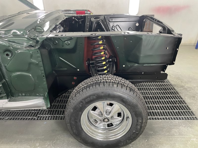
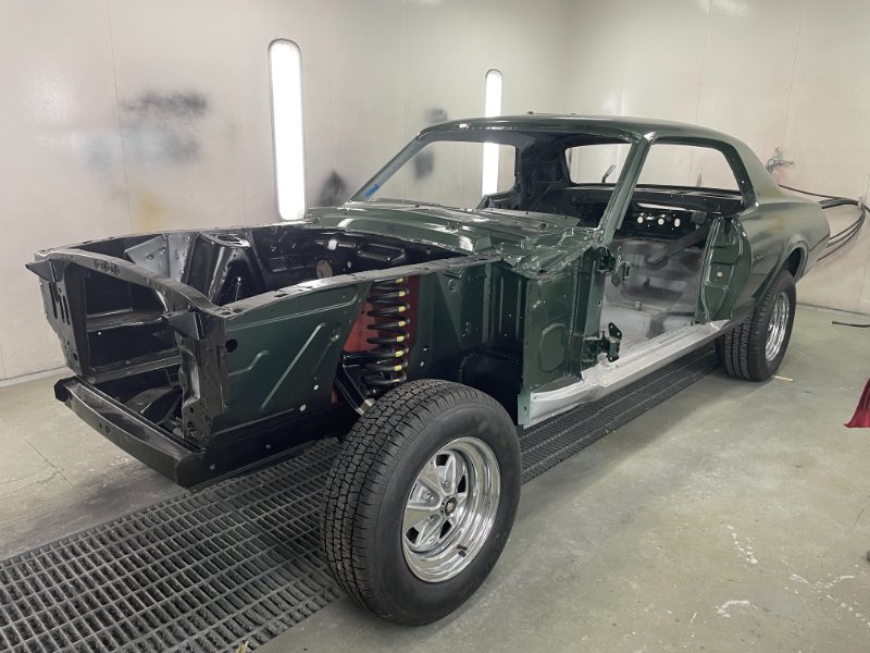
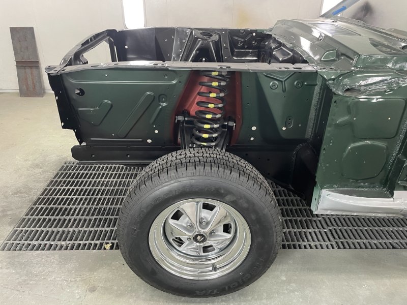
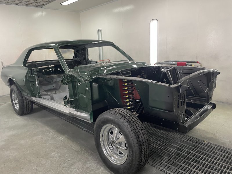
A little sneak peek at where we are now. We finished the engine compartment paint yesterday morning and installed the suspension so that we could load it on the trailer this week and bring it home. We decided to leave the doors, fenders and hood off while the dash and drivetrain components are reinstalled. Now the fun begins.
That is fantastic looking. Are you going to offer it in prints?
Thank you very much!
Not sure yet - it is up to the CCOA exactly what we do.
More than likely the Augusta Green CJ GT-E art will be used in a 55th Anniversary logo I am working on which should ultimately end up on a club t-shirt.
I look forward to seeing it and will certainly be ordering the shirt once available.
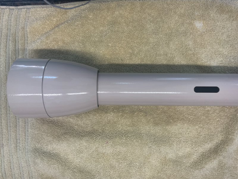
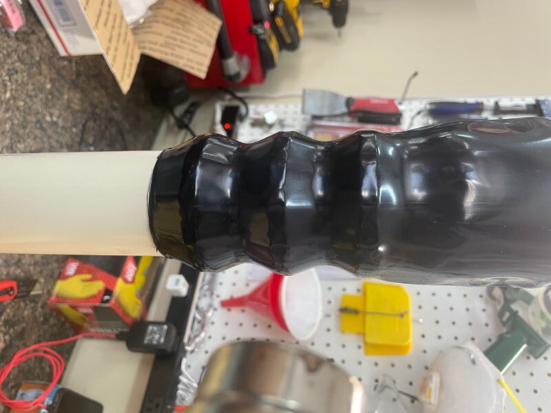
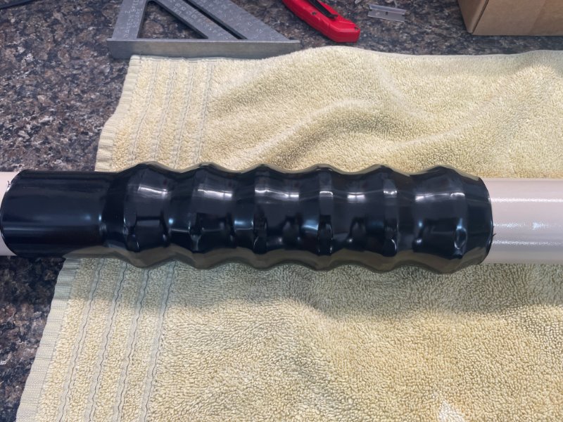
I decided to tackle the steering column today since it is now painted and it is one of the first items that needs to be put in. The column was disassembled months ago for paint and overall the components were in pretty good other than a worn lower plastic sleeve bearing and the foam insulation deteriorated. I removed the plastic coating from the collapsable portion of the column prior to paint and sourced a new “heat shrink” for the tube from WCCC. So the first step was to install the new heat shrink. I squared off the end of the heat shrink first to minimize cutting on the column. Then slipped the heat shrink over the collapsable portion of the column a little higher than needed as it was going to shrink. Then using the heat gun on low I started heating the tube starting at the top of the column and slowly rotating as I heated each ring until I got a good smooth fit to the column.
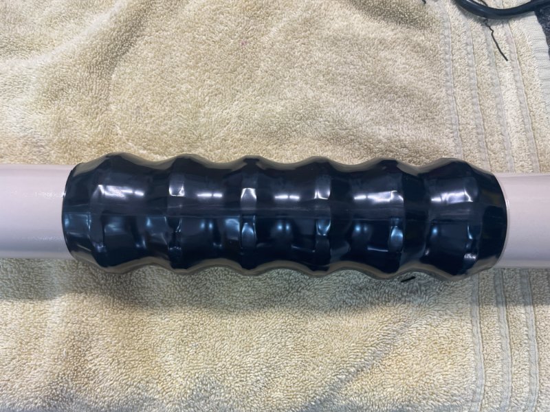
As you can see there is some excess at the bottom. Using an razor knife I followed the last groove to trim the excess heat shrink.
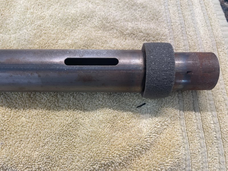
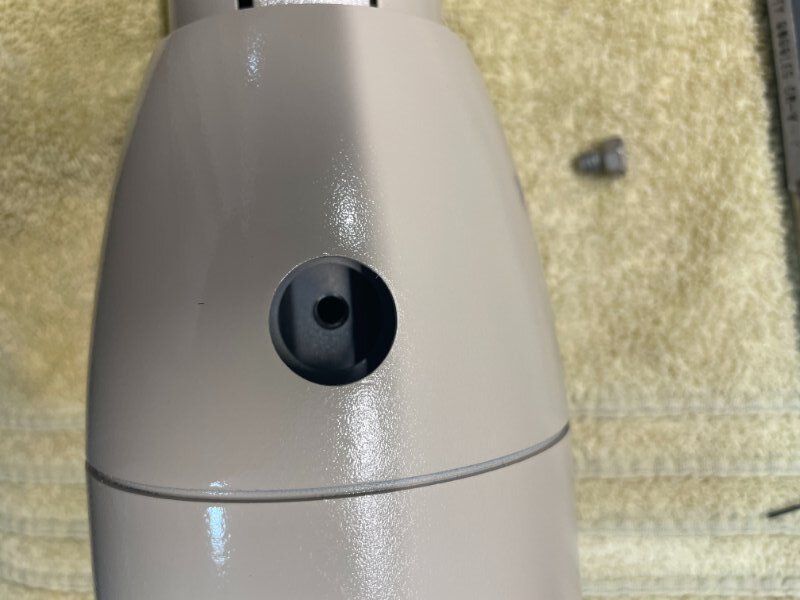
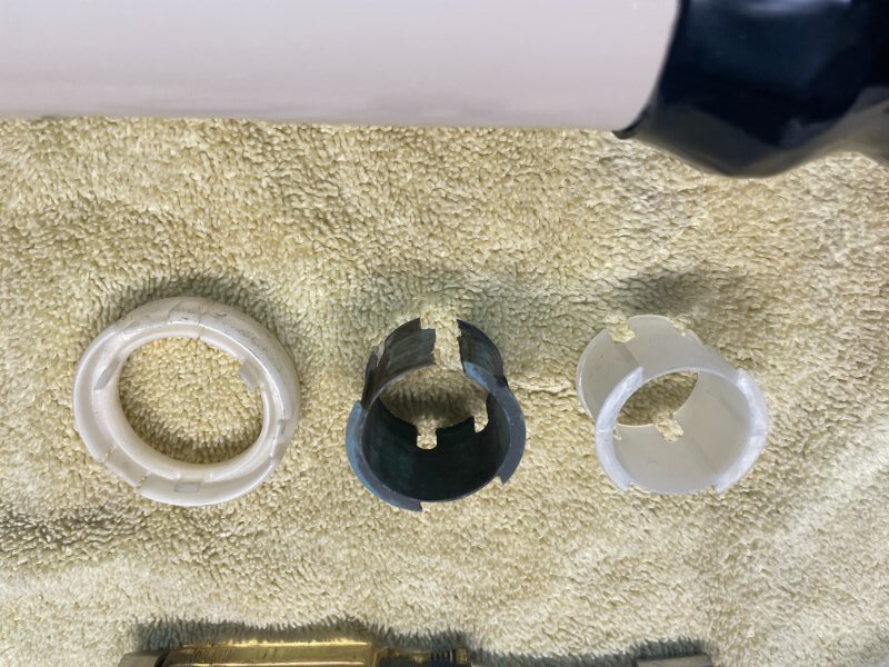
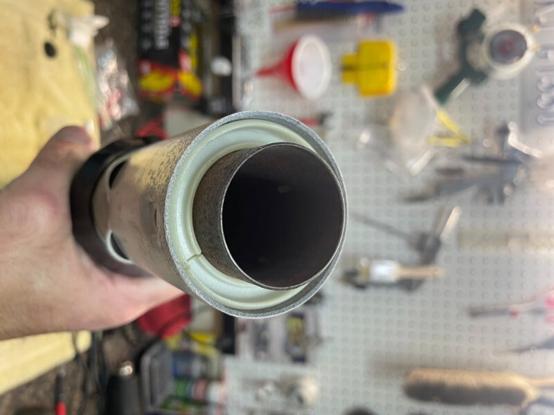
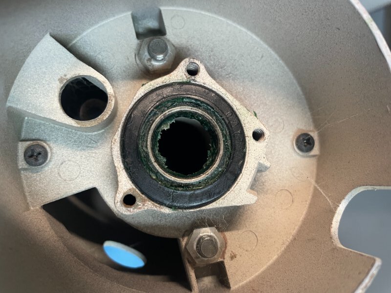
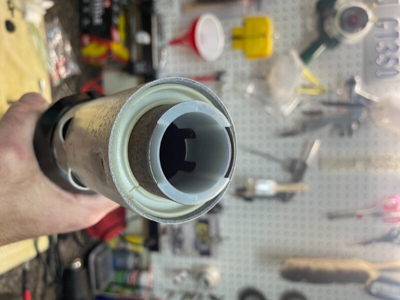
Next step is to install the inner tube which is held into the column with a 3/8" bolt at the top of the column covered by a body plug on the bottom of the column. A new foam seal was installed on the tube prior to installation which prevents dirt and moisture from getting up into the column from the engine compartment. Once the tube is installed and bolted down the large white plastic sleeve is installed to support the tube. You can see the wear on the original blue lower bearing where the steering shaft floats on it.
Finally the new upper bearing is greased and installed into its rubber housing. The lower plastic bearing is installed. The lower bearing was a little more difficult to find as it is a 68 only item. Then the steering shaft is installed into the column. The shaft locks into the upper bearing with a snap ring on the bottom and top of the bearing.
Nice job with the shrink tube.
Thanks Scott. Overall it was pretty easy to install. I was surprised when I saw that it was available. My original one was a bit banged up and hated to reuse it.
Looks fantastic. One thing, I would leave the steering column out until the dash and the engine are installed. It’s just in the way until all of that is done.
Leave out the brake master cylinder until the steering column is installed.
I appreciate the advice, thank you. I figured the rag joint would be difficult with the engine in.
Even with a big block, the rag joint is not that big of an install problem. The booster and master will be the issue. Trust me… Save yourself a lot of aggravation, do the booster and master after the rag joint and steering shaft is hooked up to the steering box.
The booster is actually not in the way and the nuts on the booster are lots easier to access with the column out of the way, as is the pushrod / brake light switch.
For the interior install, yes definitely. I figured for the under hood portion that it was much easier to get the rag joint onto the box, and the steering shaft/column hooked to the rag joint with the booster, master and brake lines out of the way. It can still be done, just a little tight, at least with my hands.
The master cylinder is the only thing you need to leave out to get to the rag joint easily.
Everyone is different but on my S code I found myself wishing I had the column out of the way when I was trying to put the firewall nuts on the booster and then connect the booster to the pedal.