Oh I don’t have any plans to take apart the other one or swap parts. It’s easy enough to troubleshoot what’s there. The coil measures good in the relay so it is most likely stuck open or has some obstruction keeping the arm from moving inside the can - if it’s in fact getting voltage and current. Will not be working on it for a few days as I am concentrating on interior appointments right now.
Continue the great work, Royce.
Not much to post for the past few days without being repetitious. I made the left side of the interior look like the right side but everyone here has already seent the RH side so it’s more of the same.
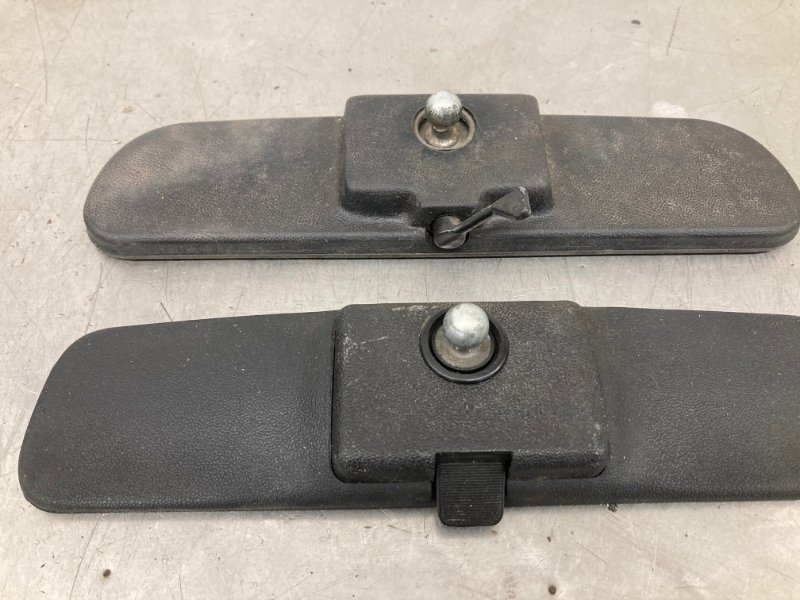
One thing really irks me - why make a reproduction part if it’s garbage? I got a new reproduction ACP rear view mirror assembly for the interior. Glued the button on the windshield before it was installed. Installed the mirror recently, along with the connecting link. The screws that came with the connecting link were rubbish. Fortunately correct looking screws came in the AMK kit.
The mirror itself is junk. It wobbles around a lot. Here’s a video of it:
https://www.facebook.com/royce.peterson.98/posts/10221049415606688?comment_id=10221049448727516¬if_id=1632443043756826¬if_t=feed_comment&ref=notif
With the engine running you can’t see images in the rear view mirror. So that has to change.
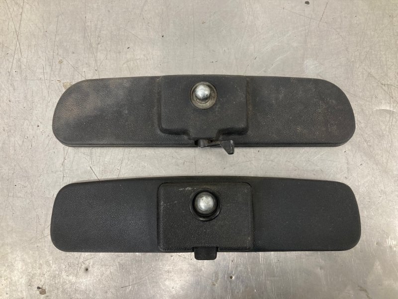
1968 was a transition year when it comes to the inside rear view mirror. I had examples of early and late style mirrors in my collection. The early style has a lever that flips from left to right to enable the day / night feature. The later mirrors are shaped differently and have a forward / aft switch on the bottom.
This car was built in June 1968 so the later one is correct. Fortunately the one that came with the car was really nice looking after I removed all the mold and nicotine from it.
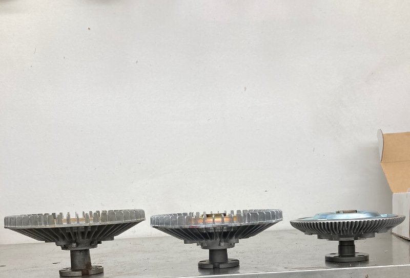
We used the C80E-B fan which uses a clutch. Here’s a sampling of fan clutches. On the right (from my personal stash) is an original C80E-B clutch. In the center is a Hayden #2711. On the left is the Hayden #2710.
The original has about 1 inch clearance from the radiator. The 2711 has about 1/2" clearance. The Hayden #2710 has 1/8" clearance.
We went with the #2711 thanks to Bill B for the recommendation.
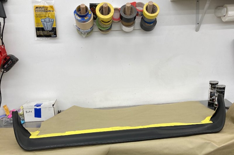
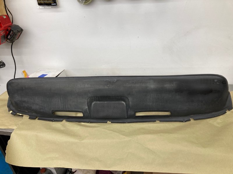
With the door panels and headliner done I turned my attention to the dash area. The dash pad is pretty nice. Straight, has all its end fasteners. No cigarette burns. No cracks.
It is severely faded on top so we begin the process by cleaning it with alcohol and tack cloth until no more residue comes off. This means the tack cloth no longer changes color - it stays white.
If the whole thing looked like the underside I wouldn’t touch it. However the top side is faded badly as we will see.
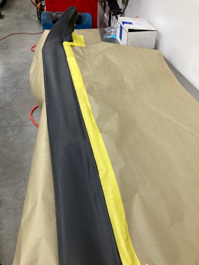
I put a coat on the underside first, very light because runs can’t be fixed. I let each coat dry for a few minutes, then apply another light coat. I am doing this in the air conditioned shop wearing a respirator mask because I don’t want any bugs or dust in the paint.
After the underside dried for about an hour I flipped it over and used the same process on the top side. As you can see it was really faded.
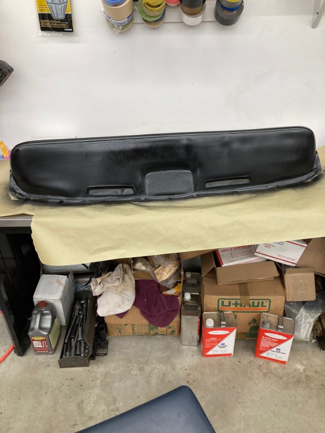
It was wet when I shot the last photo. Will let it dry until tomorrow to see if it needs more.
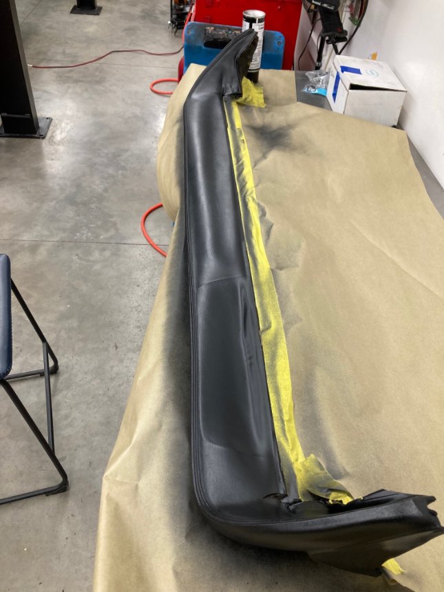
I gave it one more coat this morning. After drying for a couple hours it looked really good so I installed it.
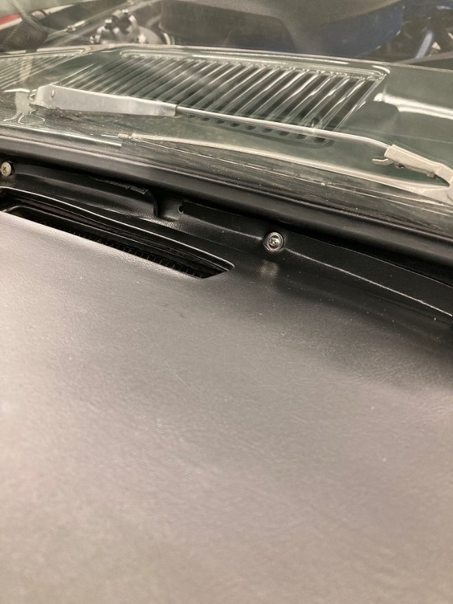
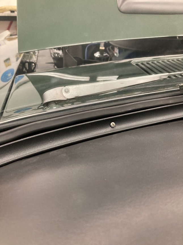
There are six nuts that secure the top of the dash pad to the dash. There is one nut in each of the two lower corners that secures the dash pad to the dash.
At the very front of the dash pad there were originally four self - drilling screws that hold the dash pad down so the trim can easily be installed. These have a rather random hole pattern. In my case two of the holes lined up. Two other holes had to be drilled. These are important and make installing the trim relatively easy.
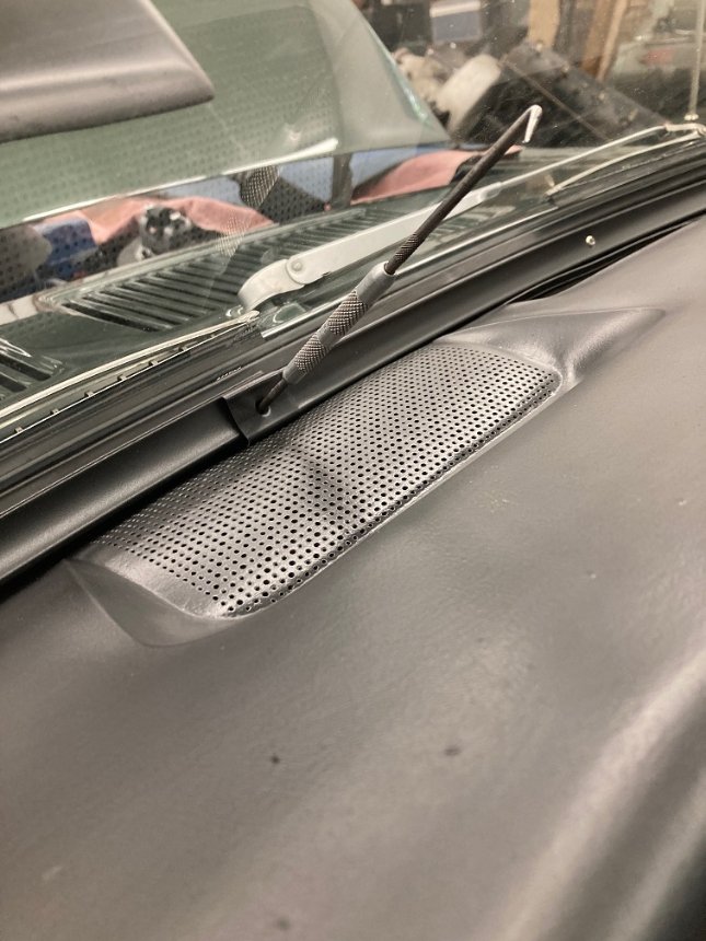
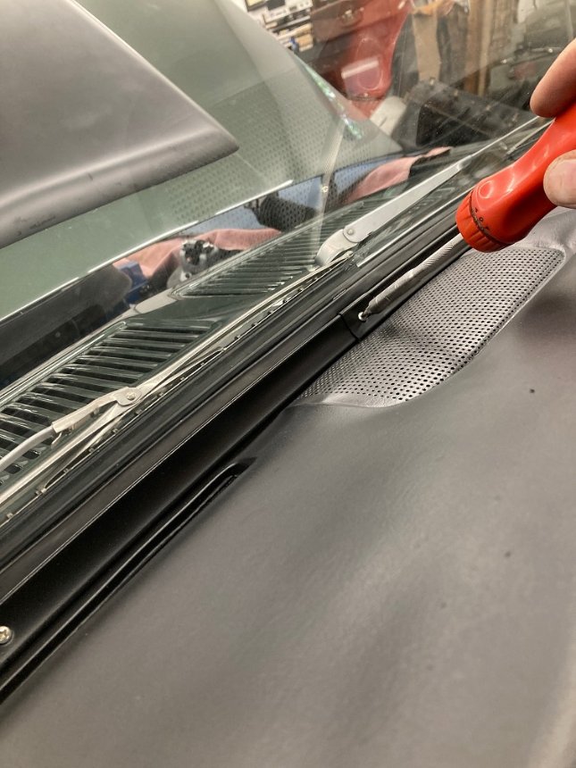
The dash trim can be a nightmare to install. The holes are pre - drilled in the dash and the pad is notched out for the holes. I use a scribe to align the holes and the trim, then install an adjacent screw. Each screw is just started in its hole until all screws are started in their holes. A magnetic screwdriver is absolutely necessary here.
When all screws have been started they can be tightened. I start at the outboard corner on the LH side first. When I reach center I move to the outboard RH side. Each screw is tightened until the head is just flush in the trim. Running these in with an electric screw gun will yield embarrassing results.
Today I worked on a list of “squawks” that I had made for myself. Things that had issues, even though they were supposed to be done. The first one was easy. The steering had a clunking noise when the wheel was turned slightly. It turned out the rag joint wasn’t secure on the steering box shaft. Easy fix, just tightened the bolt.
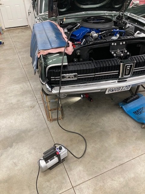
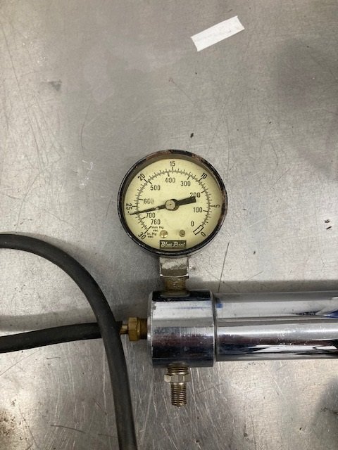
Not as easy to fix was the tilt - away steering which tilted just fine but didn’t do the “away” thing when the door was opened. For starters I bypassed the solenoid valve, connecting the tilt column actuator directly to the vacuum from the reservoir in the RF fender. I turned on the vacuum pump and it immediately flipped to the right. The actuator was good.
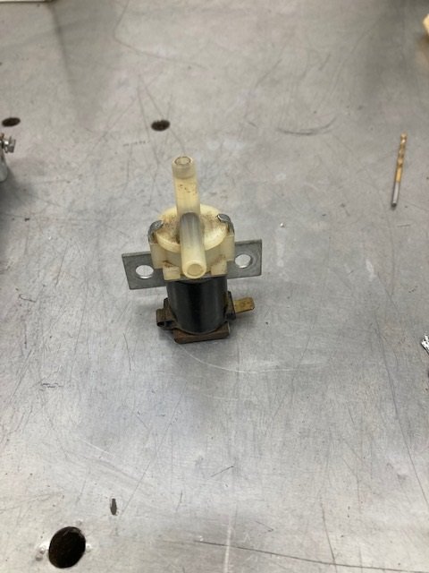
I pulled the relay and the tilt - away solenoid actuated vacuum valve. The relay tested good. The vacuum valve didn’t work, although it made a buzzing noise and the coil measured correctly with an ohm meter (28 ohms).
I disassembled the valve. Everything inside looked to be in good shape. I cleaned the inside anyway with contact cleaner and a cloth. Then reassembled the valve. It still doesn’t work. I even tested my vacuum pump to make sure it was capable. It was pulling nearly 28 inches of mercury.
Looks like I am in the market for a replacement.

Again thanks for posting pics through your project royce. Its the little things like this picture that are invaluable. I did not know there where two screws to hold the pad it self down rather then just the trim, I dont recall it being shown in the books(maybe it is and I missed it) I did not take my car apart so I had no idea these where there and fought putting the trim on without them. Having a repro dash pad they may or may not have worked but I would have tried to put them in If I had known they where there. I may not have a high end rare cougar and I make changes to mine but I do like to put it together the right way or better. Im sure this thread will help tons of people with there projects even if they are a simple base level car.
Pay attention kids!
Can you manually pull the plunger down from the valve? If not, maybe the rubber seal inside is stuck to the nylon seat. Spray some non-petroleum lubricant into the vacuum ports and see if it frees up.
Yes the valve can be opened easily by sticking something down the middle of the opening. I took it apart, cleaned it and lubed it with white lithium grease. It barely opens but it needs to seal in the opposite direction in order to function. The way it works now, it opens enough to vent the stored vacuum but not enough to port vacuum to the column release actuator.
There are actually four screws that secure the forward lip of the pad down to the dash to make it easier to install the trim pieces. My picture only shows two of them.
That explains all the extra holes I had. I thought someone got crazy ramming screws in for the trim itself.
I called Tony Augustine to see if he had any ideas on my tilt - away solenoid situation. He said if it has a buzzing noise instead of a big “CLICK” it probably has a bad connection. Long story short: Tony was right! I hooked the solenoid valve up to the battery with clip leads and it went “CLICK” loudly and every time.
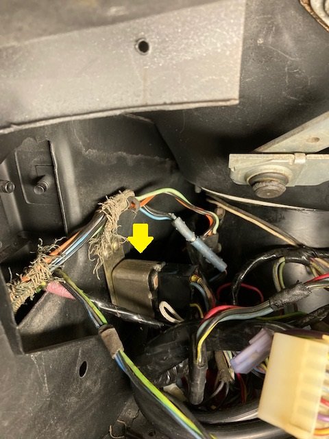
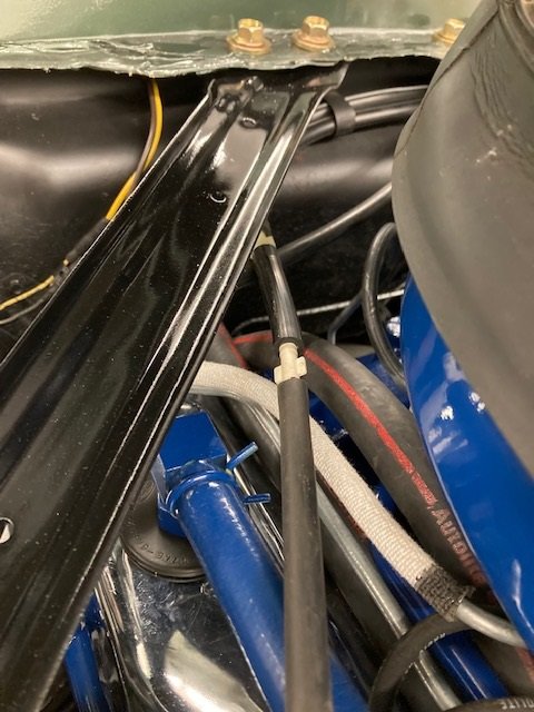
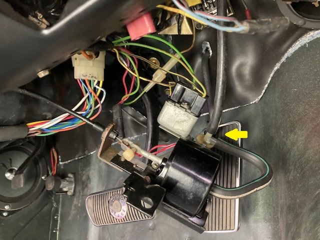
I reassembled everything in the car. It works perfectly now. Picture shows the release components not attached to the dashboard yet. The yellow arrow points at the vacuum solenoid valve.
Here’s a video of it working. I am using an electric vacuum pump to simulate the engine running.
Next I went to the Low Fuel system. Bill Basore was instrumental in troubleshooting this system. I started by using a long jumper to read ohms through the wire from the thermister to the relay. It showed 200 ohms - it should have been zero ohms. The relay for the low fuel system has been relocated (by me) so it is about 4" above where Ford put it (yellow arrow). And it is now upside down from its original position to make it easier to remove or install.