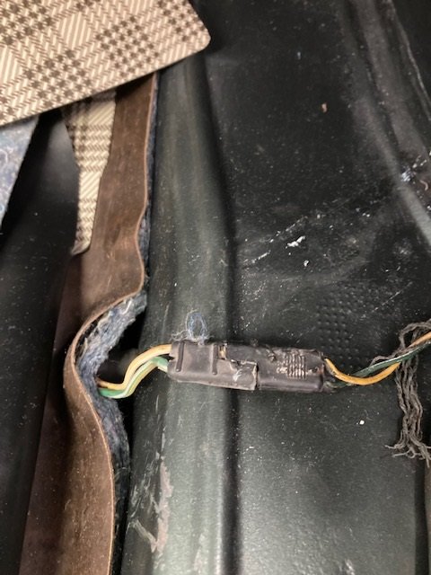
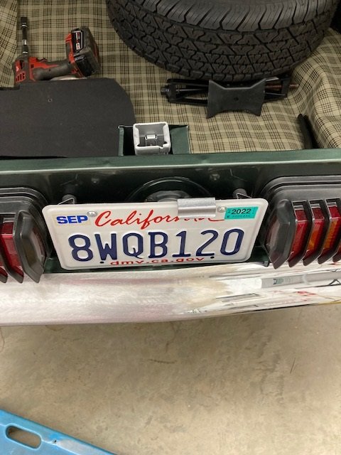
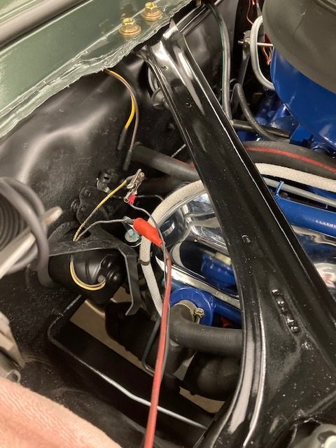
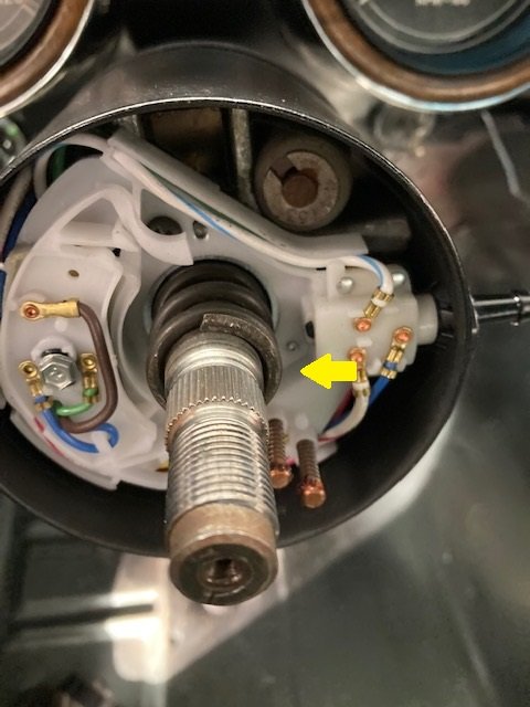
From the female side to the connection at the fuel sender it read 200 ohms. From the male side to the relay it read zero ohms. The connector is shown with a yellow arrow.
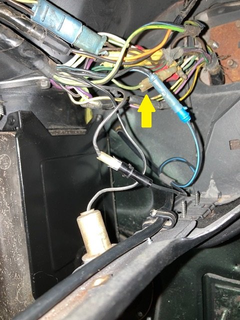
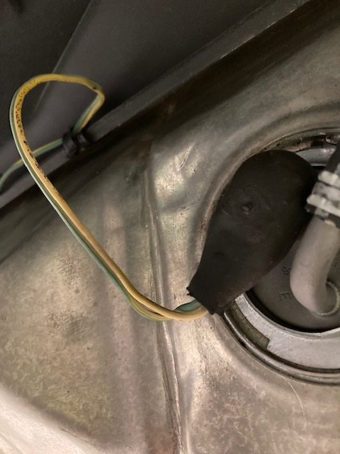
Only one connector was left - the one under the spare tire, and under the trunk mat. Turns out the female side was corroded. I cleaned the inside of the connector with a drill bit until the corrosion was gone.
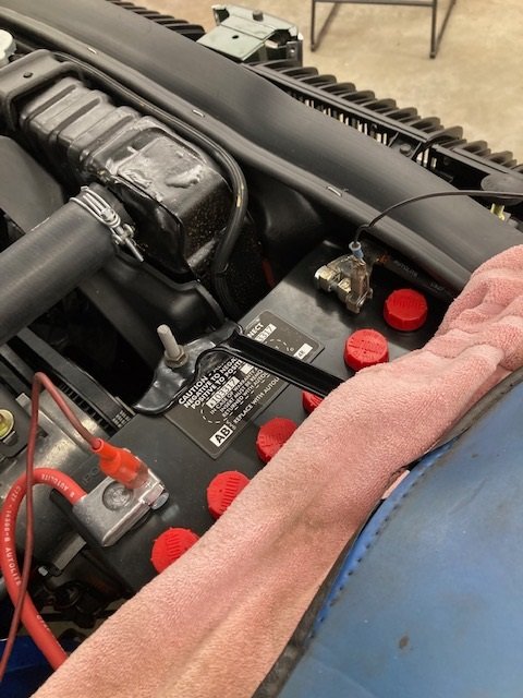
I tried it with an extra low fuel / sending unit. It worked! Then the real test. The gas tank had less than a gallon of gas. I put the connector on. Then turned the key on.
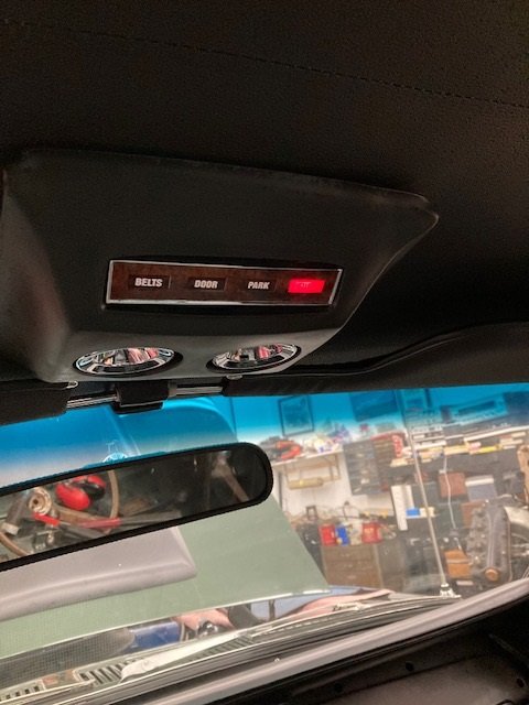
Woo hoo! Success!
Nice job Royce!
Glad that you got both of those problems sorted, Royce.
This was a real head scratcher. Usually a bad connection has so much resistance (an open circuit is infinitely high resistance) that you can’t get the relay to pull down when you short the low fuel wire to ground. In this case it did.
These old cars continue to amaze with new and different ways to baffle frustrate and amaze.
In each of these cases my post only says what I did to fix the problem. Many more unsuccessful things were done in the pursuit of functionality that turned out to be a waste of time. I try not to describe things that won’t help. ![]()
Good point.
I think all my years doing product development has left me permanently scarred. I am always looking for modes of failure. In hind sight you always think that you should have anticipated that some weird thing would happen under some strange set of circumstances, and it should have been obvious.
This is a rather extreme example but TWA flight 800 is an example of “fuel quantity indication system” aka fuel level sender gone wrong…
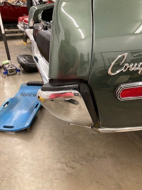
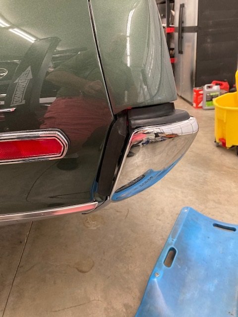
Back a couple months I had trouble with the rear bumper. It just did not fit right. I initially thought the trouble was with the car. I compared the rear bumper to the one on my GT-E and it turned out the bumper was not properly shaped. So I took it back to the chrome shop for rework.
They straightened it and asked me to fit it prior to plating. Well it is better but still needs more contour. It should clear the license plate by about 1" at the center. It is currently about 5/8" so it has about 1/8" clearance at each end.
Nearing my last electrical problem before installing the dash. I wanted to make sure everything worked prior to installing the dash and the console because they limit access so much. I have two electrical maladies left, one being the heater blower motor didn’t run. I started by examining the schematic.
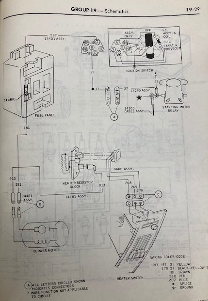
It seems pretty straightforward. The blower motor gets power from the ignition switch, through a fuse, on the brown wire. Ground is through the control panel and the resistor to the yellow wire at the blower motor. I connected clip leads directly from the battery to the blower motor. It worked fine. Checking the resistor in the heater box, it had resistance where it should and it was not loose and the connections were flawless.
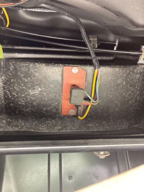
Looking at the schematic again I realized - the schematic didn’t show a ground. The ground was achieved by installing the panel. I used a jumper to simulate my theory and it all worked fine. I had been chasing a non existent problem.
Well I have been out of town helping to get an XR7-G ready for the Concours D’Elegance in Conecticut next week. Finally got back on this project today.
The R/H dash was installed after carefully protecting the painted surfaces with 3M Painter’s tape. I tested all the components and they worked properly so the screws went in.
Note that the screws that come with the AMK kit fit properly in the OEM clips or the supplied AMK clips. If you have a reproduction dash pad you will need to replace all the clips with the ones in the AMK kit. Otherwise your screws won’t fit.
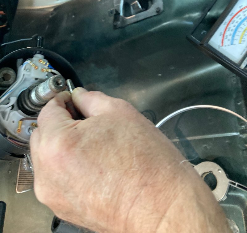
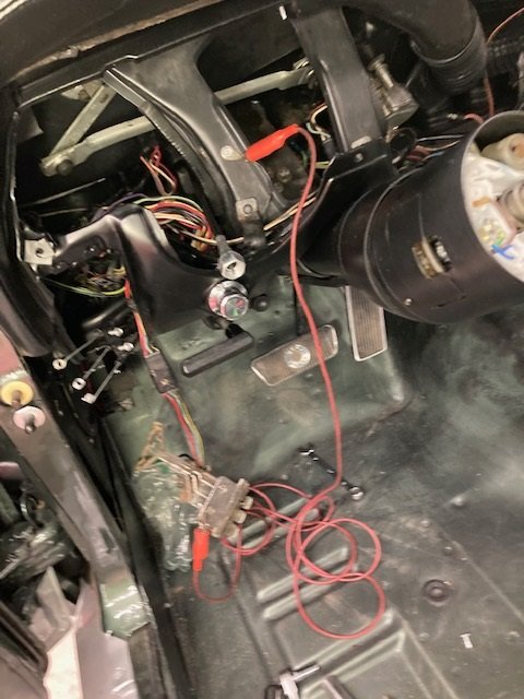
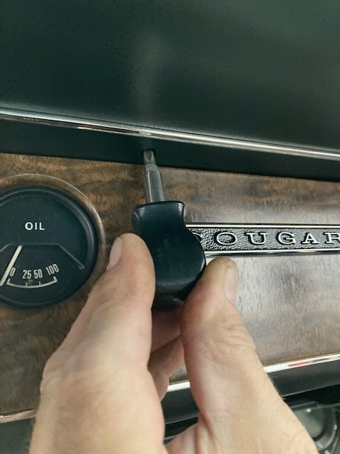
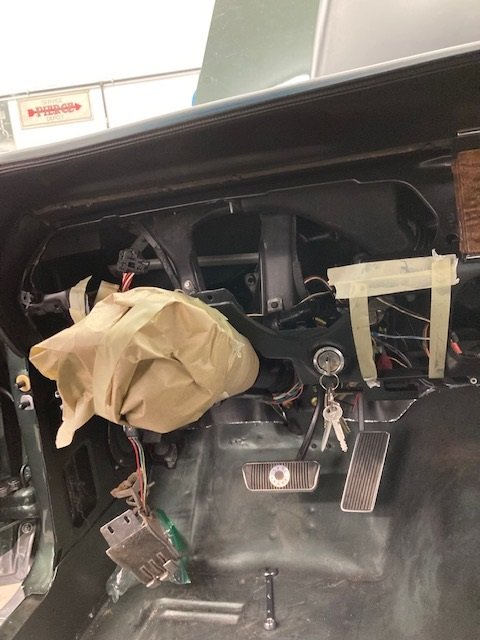
The LH dash is more complex. I started by disconnecting the speedometer cable from the transmission in order to get enough slack to hook it up to the dash. The plastic gear is removed by sliding the metal clip off.

The dash was again protected in the painted areas with 3M Painter’s tape. I masked off the steering column so it wouldn’t get scratched.
The tachometer wires can be seen through the ash tray opening and hooked up. You have to reach through the heater controls opening to hook up the wiring and the speedometer cable on the other end. I hooked everything up, then temporarily connected the battery to make sure it all worked. Once I was satisfied with the functions I put in all the screws.
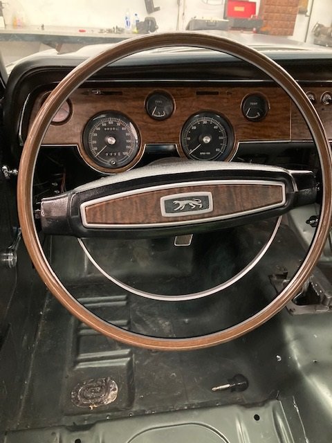
We got a “Best in Show” steering wheel from NPD. No surprise, it was assembled improperly so that the horn terminal outer ring was shorted to ground. Apparently the only #6-32 screws that are available in China are 1/2" long. To make the assembly appear correct the Chinese workers install a washer on each screw. The washers short the horn ring to ground.

The fix is easy. Just remove the screws, discard the washers, and cut the length down to 5/16" grip length. Then reinstall the screws.
Notice the spring between the steering wheel and the turn signal switch? That spring keeps the upper column bearing in place. Make sure the spring is there.
The steering wheel does not come with a turn signal cancelling cam. Make sure it is in place. The horn rings get a coating of white lithium grease before the steering wheel is installed.

Been out of town so just got back on this project after a 10 day hiatus.
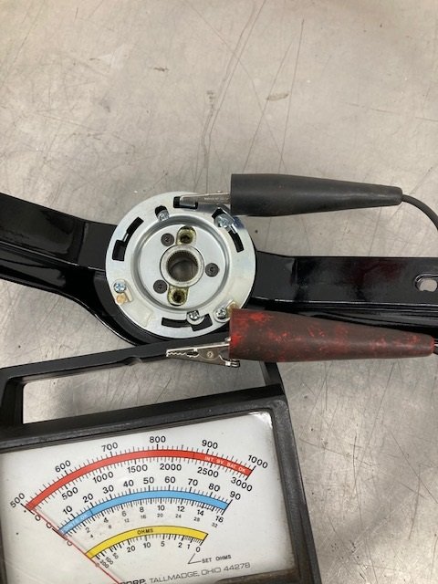
With the steering wheel installed the horn didn’t work. I removed the steering wheel and verified battery voltage (1st picture) on the horn spring loaded contact and that the horns honk just fine if the two contacts are shorted to each other.
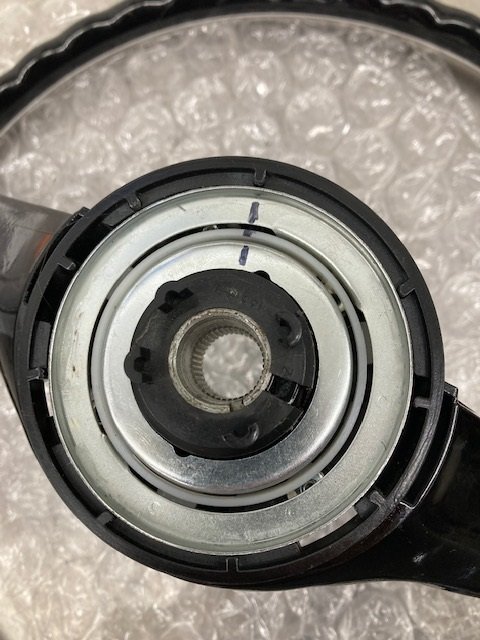
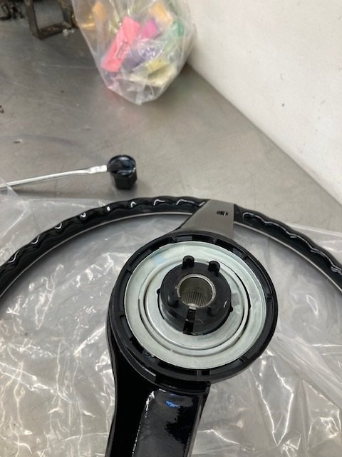
I compared the steering wheels horn contact rings - an original versus the reproduction. Not surprisingly the reproduction horn ring is recessed in the wheel about 1/4" higher than the OEM one. To make matters worse the reproduction turn signal switch has horn contacts (spring loaded) that are about 1/16" shorter than an original one.
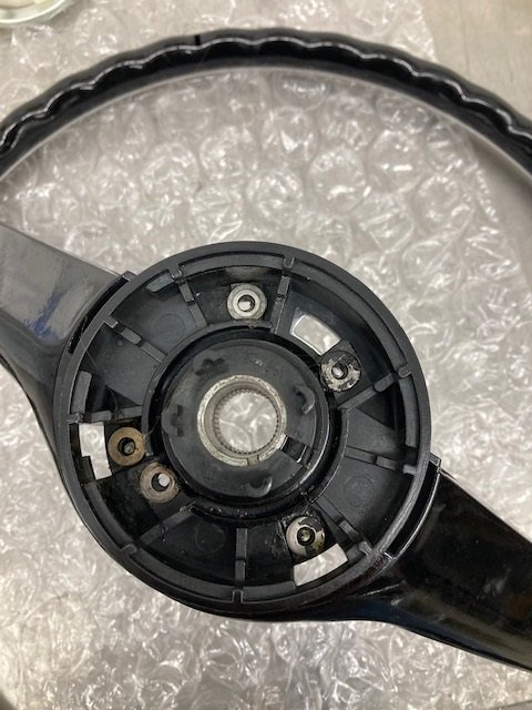
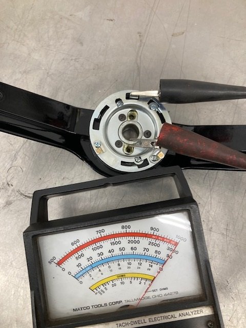
So the total difference is about 5/16". I marked the slip rings and plastic isolator with a Sharpie prior to removing them. It makes reassembly a lot easier (second picture).
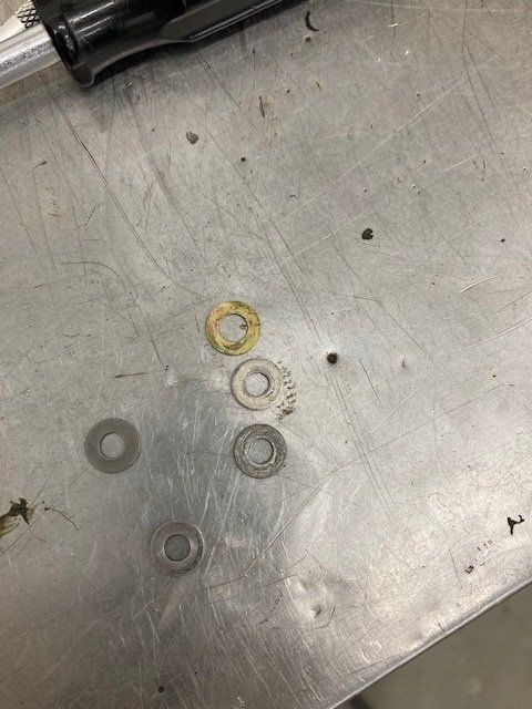
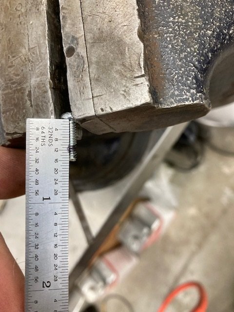
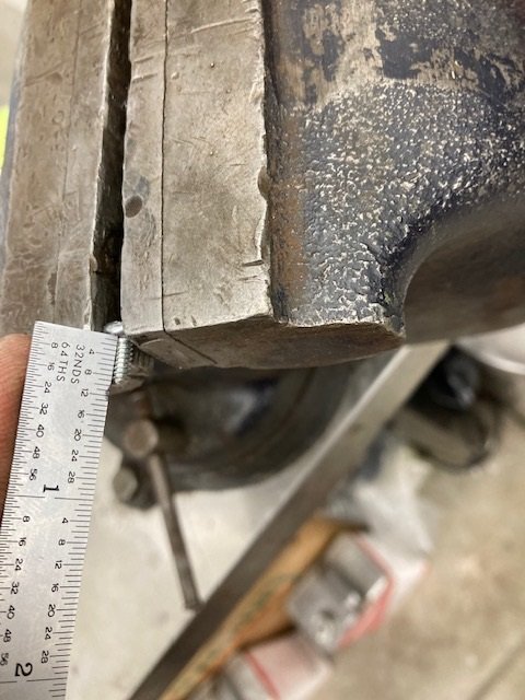
I was able to shim the horn rings about 3/16" before running out of screw length. I glued AN960-10 washers to the steering wheel in 5 places. (third and fourth pictures) Ended up with 2 washers under each screw. Had I not cut the screws off they would be long enough. As it is right now the contacts occasionally contact the steering wheel slip rings. One more washer ought to make it right.