Scouring through the myriad posts on console electricals I still sit here scratching my head as to where to start. I’m hoping I haven’t already bitten off too much. On the drill down I have three main questions. 1) Is the circuit board supposed to be “tight” to the console base? Mine has buckles in it in places, pinned tight in others. 2) Can I test the lamps individually with 12v, or do I have to keep myself down around 5v? 3) I presume (gleaned info) that I can test the individual gauges (really just need to verify temperature gauge) by putting 5v or less to one post and ground to the other.? Appreciate any advice - also considering reconnecting the battery and testing the pin connectors on the console plug - I did find this relative to an XR7 and am hoping it will be the same for my base model:
“A voltage check with key on, has 12 vdc on pins 5, 6, 10, and 12 which looks correct. Pins 1, 2, 4, 7, 14, 17 and 18 have continuity to ground.
Pins 1,2,4, 7,14 and 17 may show continuity to ground because there’s a lamp in the circuit, and it only has about 1 ohm of resistance.
Pins 5, 6, 10, and 12 should show 12V; the first 2 at all times, pin 10 when the key is in RUN, and Pin 12 when in ACC or RUN.”
Dash lamps require 12V or less; I’d use the full 12V to test them.
Testing gauges while attached to the circuit card is difficult. For 69/70, the dash cluster is metal, and the gauge posts can easily contact the metal housing (ground), screwing up the oil, water, and temp gauges, as they are all tied together with a 5V input. Do not test by applying 5V on one side and ground on the other until you are sure there is no ground to the metal housing. You can check for this ground by measuring the resistance of any post (except ammeter) to the dash cluster housing: if 0-1 Ohm, there is a ground on that circuit. If approx. 14 ohms, another post on that circuit is grounded.
You can’t test gauges with a multi meter. They are incredibly easy to test when the cluster is plugged in using The Gauge Tester. It costs $30 but it is the right tool for the job.
the instrument voltage regulator puts out pulses of 12 volts that average to 5 volts over time. The sender side needs to be terminated into 10 ohms to read full. If you remove the gauge entirely 2.93 volts will drive it to full.Gauge Tester GT-Ford-1 | Desert Classic Parts
Assuming you are talking about the dash instrument cluster printed circuit, that connector has a completely different pinout for the XR7 than for standard Cougars.
It won’t hurt that the printed circuit has warped and is no longer flat, as long as all the contact locations mate to the bulbs, connectors, etc.
The gauge tester really is a better way to test and calibrate gauges without damaging them. And it also tests them out along with all the wiring and connectors between the gauge and the sender units.
Midlife, Xr7g428, Calicat: Thank you all - I’d just like to do/replace whatever I need so I don’t have to go through this again anytime soon. I have an underdash nightmare electrically as well, and dashpad repairs. Speedo and Fuel gauge are the only things that work in the main console, door ajar and lights warnings in the center console.
Bill, I do have the gauge tester, and have used it; it’s great. Temperature gauge only works (pegs) through the oil sender and doesn’t show anything through the water temp sender (I did try reversing the wires, no effect). Again, I’m just trying to cover all the bases.
Craig, do you know what the “pinout” is for the base model? Or where to find it - I don’t see it in the shop manual; but I frequently have issues finding things in there.
Yikes - sounds like your wiring has really been hacked up. If it were me, I would just pull the wiring harness and have Midlife restore it. Not an easy job, but otherwise there is nothing to document what you have in the car now.
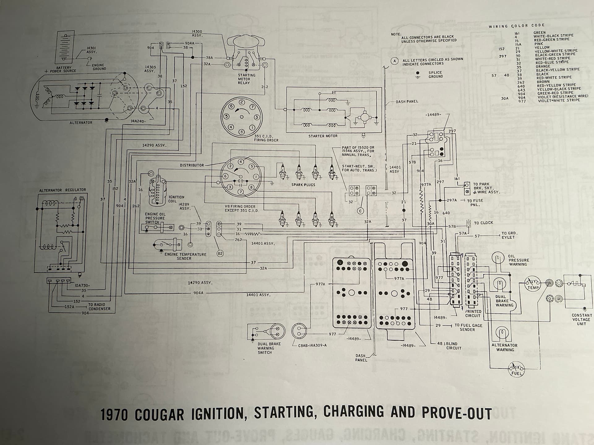
The pinout of that printed circuit connector is spread out among several pages of the 1970 Mustang and Cougar Wiring and Vacuum Diagrams. I just bought this copy and it’s SO much nicer than the smaller copies of copies that I had used previously:
Thanks for that! I was just looking at the one from WCCC and if I blow up that section I can actually read it - but I’ll still have to chase the routes down and reannotate it. The EBay one might simplify matters. I am so hoping NOT to have to pull the harness; I may have already made this a parts donor vehicle! There are so many hacks and splices in this thing it boggles me. I found two rheostats behind the glove box that I have NO idea what they are controlling (PO installed, not factory) and the after market stereo, speaker, and amplifier are all pig tailed in. I’m starting by nixing the radio - I’m not a noise pollution fan. I may take some snap shots.
Do you know: If I protect the gauge studs (slip a tube over them) is it safe to put the console back in the car, plug it in, and reconnect the battery? Or am I begging for more problems….
Yeah, it is very hard to say. Just don’t know what is hooked to what until you spend the effort to trace it all out. Easier said than done, I know. Have you had the car running with that setup before?
Oh yeah! I’ve been driving it without issue since I took care of the drive line; this started because I was aggravated about not having my parking brake warning light! I should have just “dealt” with it (maybe). But, I’m also relying on accessory gauges for ammeter, oil pressure, and water temp. The biggest problem for me right now is OVERWHELM. I need to put my brain on ice, and pick one enemy at a time. That being said, I assaulted it today checking continuity on three circuits: oil sender, water temp, and parking brake. I’ve got continuity sender to pin connector on all three. #4 pin is oil sender (white/red); #5 is water temp (red/white); #14 is emergency brake (green/red). Problem is reading the WCCC gauge schematic it shows oil sender at #15, water temp at #13, and emergency brake at #9. Can you look at your schematic and see what it says for those three circuits? I’d appreciate it (needless to say).
That’s the way to do it - one circuit at a time. But I think you are looking at the XR7 schematic. Standard Cougar looking into contacts of the plug (numbering starts on the lower right corner opposite the molded bump):
Emergency brake warning light = #14
Oil warning light = #6
Water temp gauge sender = #4
Brake failure warning light = #7
Fuel level sender = #16
The warning lights all get grounded by the various sensors and switches to light the light. The fuel and temp senders are variable resistors.
I guess instead of just reading the titles of the pages I should have consulted the index. I was on 2-E14 which does show in the index as XR7. Interesting though that by your decipher my emergency brake is fine but both my oil light and temperature gauge are in the wrong locations. I’ll have to rifle around and see if something got “spliced” wonky. Thanks!
Indulge me if you will: you’re finding #14 as parking brake, I see it as an unused pin in the schematic (but #14 on my plug tests for PB) I see it as #7 on the schematic. What am I looking at wrong?
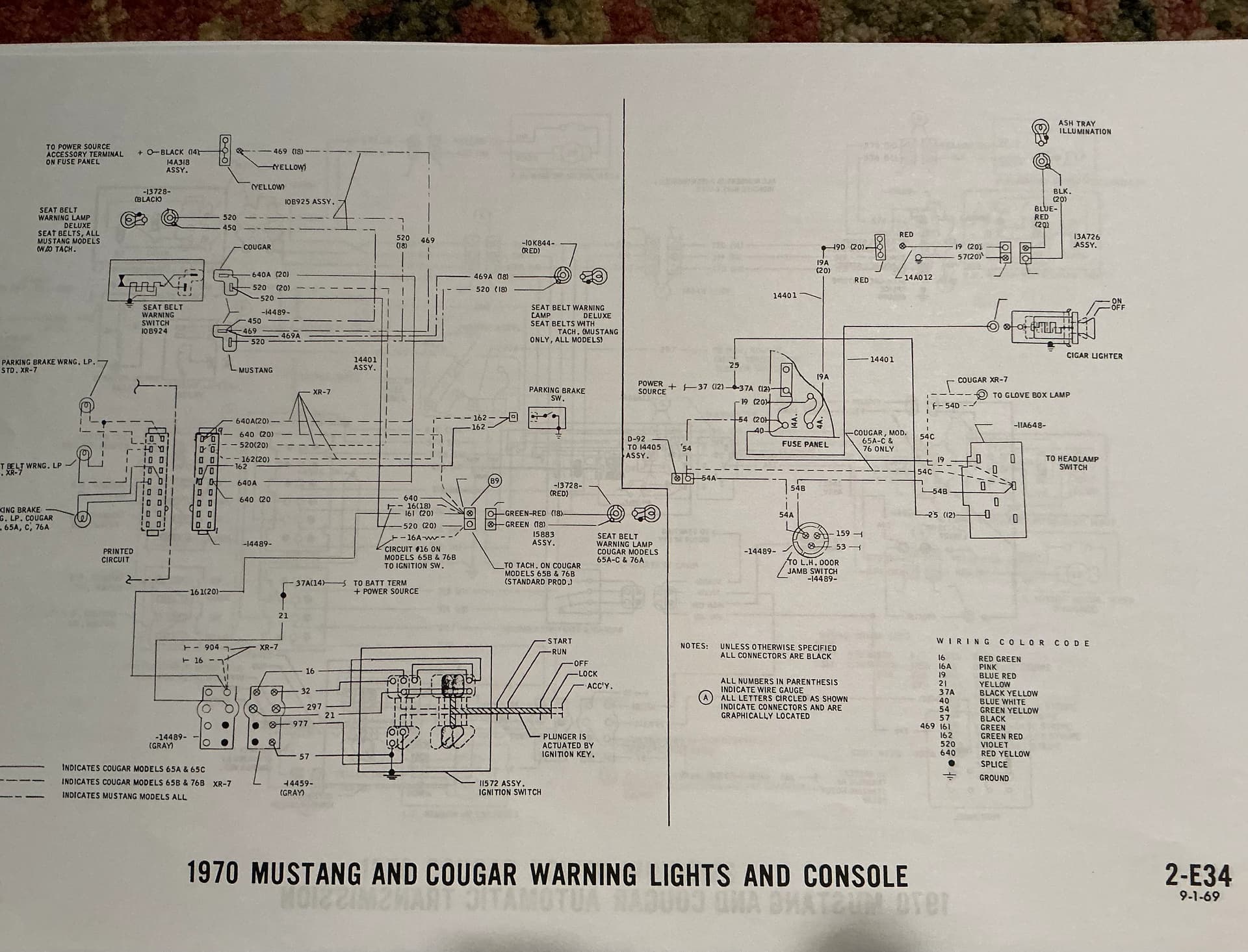
In spite of what the index says, I believe page 2-E12 is for the standard Cougar and 2-E13 is Cougar XR7. 2-E14 is a continuation of 2-E13 which applies to Cougar XR7 with gauges. Good point on parking brake light - it is on page 2-E34.
Check that! They really bounce you around on that don’t they. Is the EBay booklet the same? Or maybe a little more refined. It will take awhile, but I’ll figure it out - thanks for the help!
I hear ya - couldn’t have made it much more confusing if they had tried. My pics are from the eBay booklet. I have another smaller booklet dedicated to just the Cougar and it is smaller copies of 2-E12 for standard Cougar and 2-E13/14 for Cougar XR7. So the schematics are labeled correctly, just indexed wrong.
That’s a scary thought; met a guy the other day at a rally, about 80 years old, trying to sell his “unfinished” restoration; not admitting to dementia, but can’t bend, can’t grab, can’t see, can’t remember - YIKES!