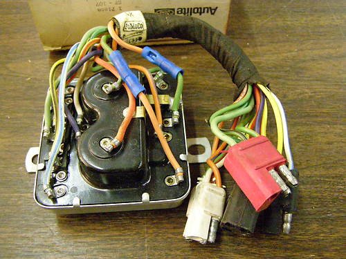
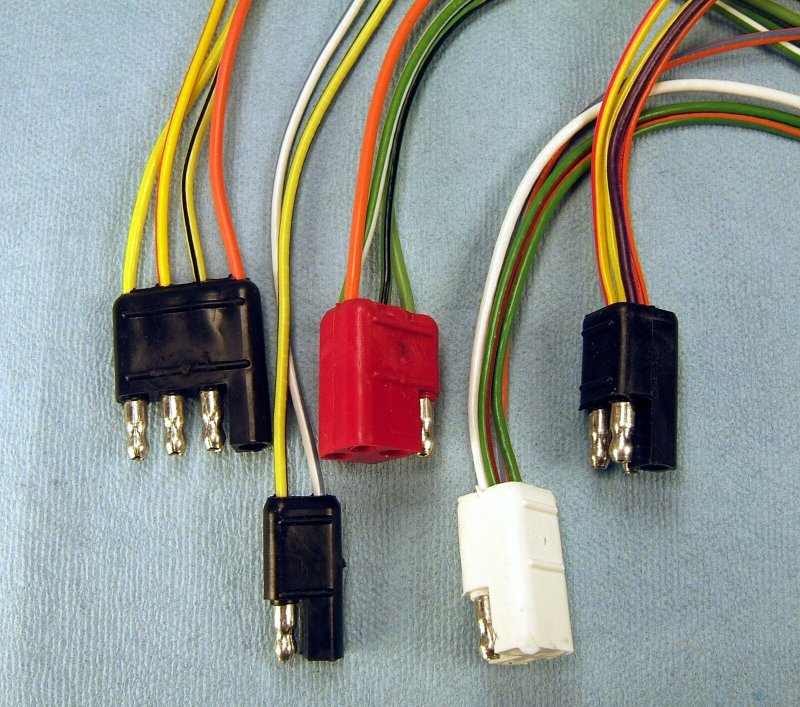
Thanks for the feedback. I do have a 68 harness but it is missing the pigtails/connectors in the trunk. I am thinking about adding them to repair harness. I do have a questions regarding the D3 Red connector. The schematic shows the following.
Thanks for the feedback. I do have a 68 harness but it is missing the pigtails/connectors in the trunk. I am thinking about adding them to repair harness. I do have a questions regarding the D3 Red connector. The schematic shows the following.
D3 Connector
448 = G/W
442 = O/W
444 = G/BLK
475 = G
Why is the 442 different. The schematic shows the O/W on the 446 pin for the D4 White plug.
Good catch! The existing documentation in the 1968 Shop Manual, 1968 Cougar Wiring Diagrams, 1968 Cougar Electrical Assembly Manual, and 1968 Cougar Troubleshooting Guide is WRONG! It does not match how the harnesses were built!
I suspect that the wiring harness product engineer and the relay product engineer didn’t catch the mistake until later on because I’ve seen a number of used and NOS K8/K9 relays with two blue butt connectors crimped on these relays - swapping the green/orange and orange/white wires.
I have repair pigtails available that can be used to fix your harness.
The drawings were created from “as built” harnesses and relays, so they will mate up to your existing wires.
One exception is the 475 wire. It is solid green on these pigtails.
The 475 wires were made using painted white stripes which rubbed off over time and were not visible on my 1968 Cougar.
So I specified solid green instead of green/white. Since the other green/white wire is much smaller diameter wire, it is easy to match them up.
BTW: the pigtail kit doesn’t include the emergency relay connector since my electronic sequential systems do not use the relay.
Thanks Vic,
I bought the repair pigtails. Just to confirm. With your repair pigtails I should ignore the schematic and just go color code to color code on the wire?
Got the repair pigtails. Before wiring them up i wanted to check the power/voltage coming back to the trunk. With the power in on position I am getting the following:
With left blinker switch on:
White - 4.68 volts
Orange/Green - 4.68 volts
With Right blinker switch on:
Light blue - 4.68 volts
Violet - 4.38 volts
I believe I should have 12 volts. Any thoughts on why such low voltage coming back to the trunk?
Yes, the signals should be close to 12V.
Check the same wires at the turn signal switch connector - both sides.
A significant drop in voltage usually indicates either a fried pin on the
turn signal switch connector or a bad turn signal switch.
Note that the brake power does not feed through the turn signal switch on a 1967-68 Cougar.
Right turn:
TS SW side----------------Harness side
Blue------------------------Orange/Yellow (input from fuse)
Red-------------------------Lt Blue
White/Blue----------------Violet
Orange/Blue---------------Orange/Black
Left turn
Blue-----------------------Orange/Yellow (input from fuse)
Red------------------------Lt Blue
Green/White-------------White
Green/Orange------------Orange/Black
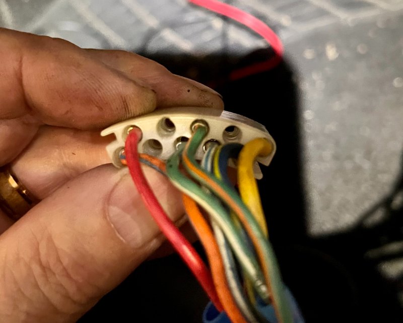
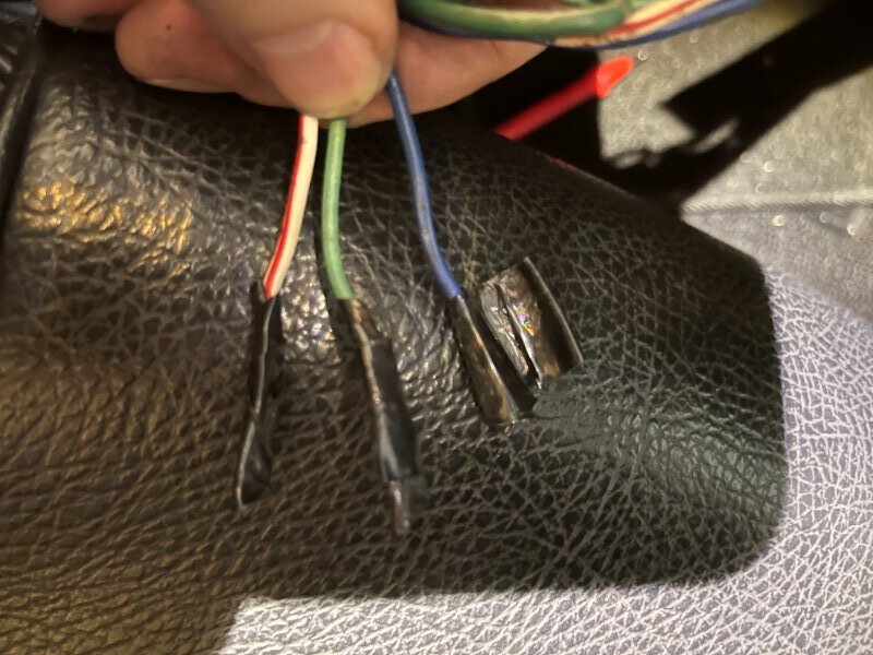
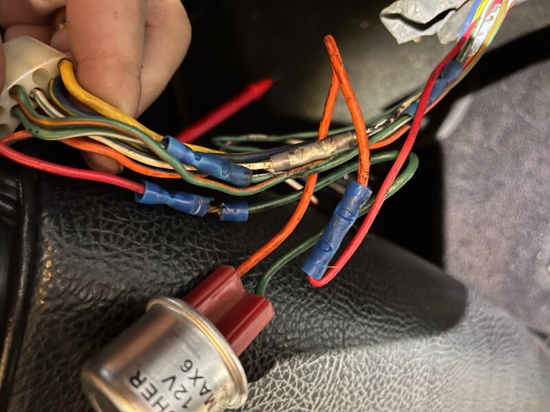
Ok where do i begin. I was getting ready to check the voltage at the turn signal harness/switch and noticed somebody removed 3 wires and added a flasher/buzzer unit. see pics below.
I believe this was done to connect turn signals directly with no sequential hardware.
Do you have a schematic or know the order of the 3 wires (assuming the all 3 go into the connector) into the turn signal harness? I am going to remove the flasher a patch the red wire back since i have all the sequential hardware.
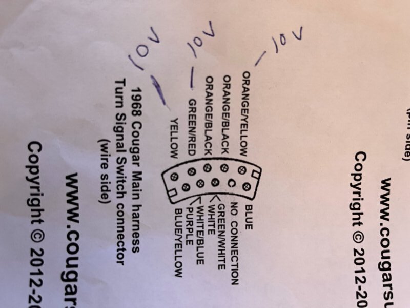
Thanks for the diagram. I have a couple questions regarding those connectors.
Wanting to confirm which wires on the turn signal main harness switch connector should have power. attached is what I have on mine when testing. See photo.
I did notice that when both end of connectors are plugged in some wires don’t match up. Like the Blue on switch connector mates up to the Orange/Yellow on harness switch connector ect. Is that correct?
Thanks for all the help. Hopefully I can get these sequential lights working soon.
Thanks for confirming those are the only 3 wires that should have power on the turn signal harness side connector.
After hooking everything up according to the turn signal connector wire diagram and wire color to wire color in the trunk connections using your repair harness kit, the turn signals are still not working. I did notice that when I activate the emergency flasher that the white and the orange/green wire gets power and the sequential motor turns on.
Do you have thoughts on what i need to check? Thanks
If the Orange/Green power is not 12V, based on your other results, the turn signal switch is probably bad.
Typically, if the motor is running and the Violet (RT turn) or the White (LF turn) is 12V but no lights,
the contacts under the white plastic cover of the motor-driven sequencer may be contaminated with carbon.
They can be cleaned with a relay contact burnishing tool or 1000 grit sand paper.
This cleaning won’t last long until they are black again. This is caused by arcing of the high current from 1157 bulbs.
That’s one of the reasons I developed a solid state sequencer. Motor failure is the other reason.
Another possibility is that the large turn signal relay (with 14-wires) is bad.
It should make a loud clunk when the right or left turn is selected.
It directs the output of the sequencer to the right or left lights. The coils burn out,
the contact arms get jammed or break off, and/or the contacts get oxidized.
Rarely, these relays can be repaired by disassembly and cleaning.
If they have ever been submerged in water, it’s best to replace the parts.
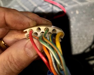
I tested and I am not getting power to anything in the trunk except to the white and the orange/green wire in the trunk when the emergency flashers are turn on. The weird thing is that i was getting power to the following when the TS SW connector was wired like the image below.* (that was when turn signals were wired directly - no sequential hardware.)
With left blinker switch on:
White - 4.68 volts
Orange/Green - 4.68 volts
With Right blinker switch on:
Light blue - 4.68 volts
Violet - 4.38 volts
It is very common to find that when a 1967-68 Cougar turn signals have been modified/rewired with flashers,
it was done because of a failed turn signal switch or burnt (oxidized) turn signal switch connector pins.
The voltages you are measuring are very low - probably due to a higher than normal resistance in the signal path.
If you still have 10V at the turn signal switch input (orange/yellow), then there is a 5V drop across the switch.
A poor internal connection in a turn signal switch or pins may only show up under load.
Test the switch to make sure the internal connections are good.
Typical resistance measurements should be less than .1 ohms.
Make sure there are no other wiring changes in the harness that feeds to the trunk.
Check the plugs just above the driver’s side kick panel - that is where the 13A449 LH tail light harness plugs into the main harness.
Other wires in the system are part of the RH 14405 tail light harness that plugs into the main harness just above the passenger’s kick panel.
The RH 14405 harness plugs into the LH 13A449 harness inside the trunk above the LH rear wheelwell.
Make sure these plugs are intact.
One last item: Did you connect the black ground pigtail wire correctly?
Ford stupidly chose to use black 18ga wires for both the running lights and the ground wire in the trunk.
Verify that these did not get mixed up.
Good News. Sequential lights are working. Vic, you were right on. I tested the switch and it is bad. I manually tested with jumpers on the Harness side of the switch for the left and the right and they both work. I have ordered a new switch and can’t wait to button this project up. Thanks for all your expertise and switch diagram.
Got the new turn signal***** installed and both left and right sequentials are working. The weird thing now is that when the left turn signal is activated, the left sequentials work and all the right turn signal lights flash like the emergency lights. Any idea what could cause this?
Another thing i just noticed. With just the emergency flashers on, the 2 outer lights flash on left/right. Isn’t it supposed to be just the center on both left/right that are only supposed to flash?
Verify that the under dash indicator relay (located at the fuse box) is grounded. It has a separate ground that attaches to the windshield wiper bracket only a 1968 Cougar. Feedback can occur through this indicator relay if it is not grounded. This feedback can also occur if the indicator relay contacts are oxidized and have high resistance.
Correct, only the center light is supposed to flash. The emergency relay may have failed with one of the contact pairs stuck.
I could sure use some help from the turn signal gurus out there. So, I have brake & running lights but no turn signals (front or rear) or hazards (front or rear). Also, my brand new grounded solid state K-5 from WCCC won’t click with the turn signals on however the sequential motor in the trunk is turning. With my emergency flashers on, there is no clicking sound from the K-6 relay either but the sequential motor in the trunk turns when engaged. Lastly, the dash turn signal/hazard indicators are not working at all. However, before I replaced the K-5 they would give me 1 quick flash when I engaged the blinkers though I still had no lighting. All my bulbs are led.
What I have checked:
A) I have my steering wheel off & tested for power at the switch when I turn left or right (blue wire on left & green wire on right). Have power & the sequential motor in the trunk turns with the blinkers engaged. Still no lights.
B) Tested for power at the 3 wires on the hazard switch disengaged/engaged (white w/blue stripe top, white w/red stripe left, blue wire right). Seemed to be fine & the sequential motor in the trunk turns while engaged. Still no lights.
C) Obviously all fuses test fine.
Any assistance or check this-check that, would be very much appreciated!
Typically, if there are no turn signals front/rear flashing while the original sequential motor is running,
the contacts under the white cover are oxidized with black carbon and not allowing power to the lights.
Current through the K5 relay to the lights is detected and used to flash the dash lights.
What LEDs are you using? The lower current used by the LEDs may not punch through the oxidation on the contacts.
It is possible to pull out the contact assembly, clean the contacts, and buff them with a relay burnishing tool.