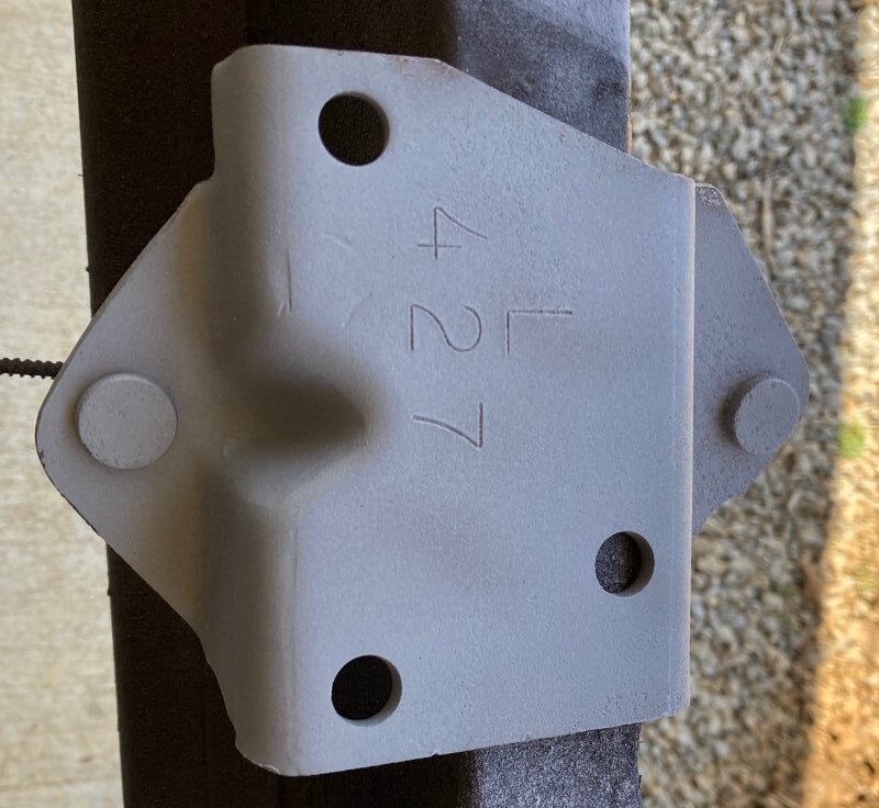
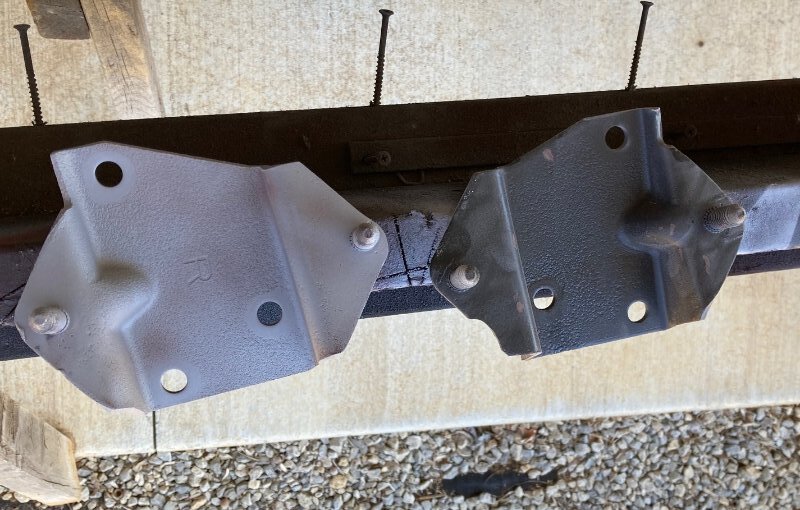
Today I kept on working on engine associated parts. The 427 GT-E has a unique engine adapter plate bolted to the block on the driver’s side to clear the side oil passage. The RH one is like any 390 or 428. Someone had painted them black over the years so I had to bead blast them and then spray matte clear so they wouldn’t rust.
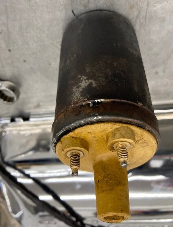
This is a super original car and many of the parts are worthy of restoration like the coil. This is the “Before” Picture.
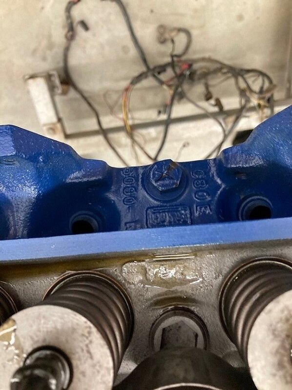
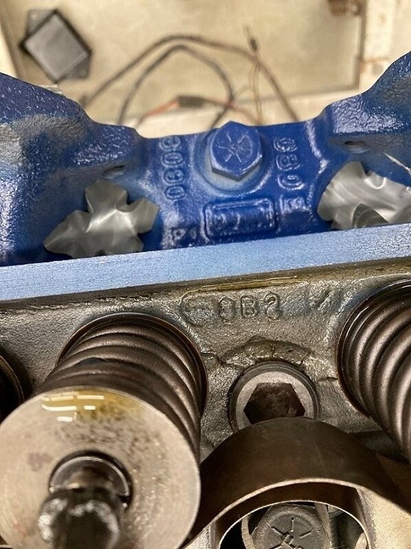
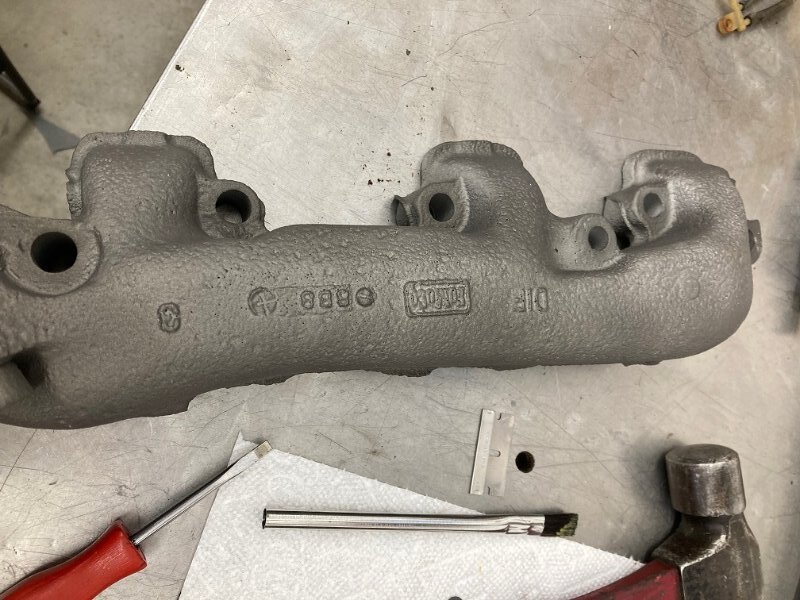
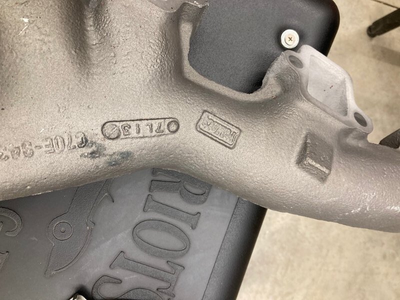
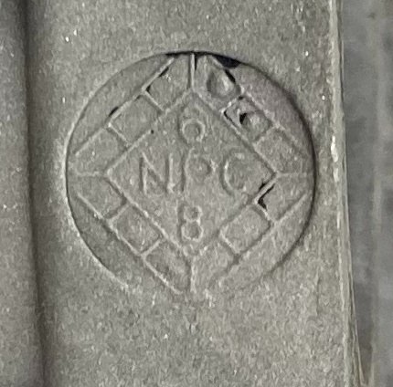
The car was actually built in March 1968 so it has the C80E 6090-N heads as expected, drilled for 390GT style exhaust. Both sides were dated 8B2, with one being a bit muddier than the other.
Hmm unable to attach photos - Bill maybe something wrong with the default settings?
Just found out it is limiting my photos to less than 800 pixels high and less than 500 pixels wide. Around 200K - that’s weird.
What error message are you getting. I have not changed anything.
Deleted
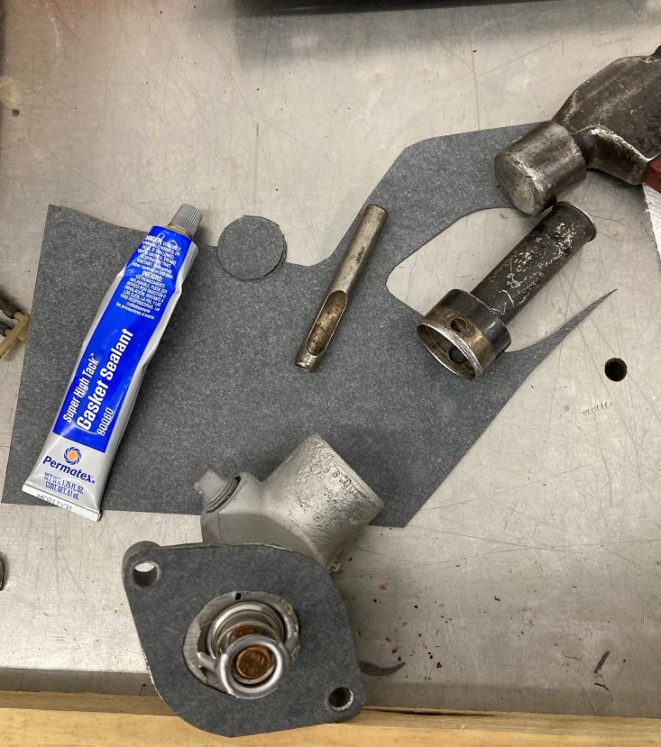
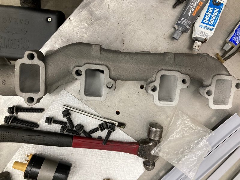
I drilled a 3/32" hole in the thermostat. Made a gasket, installed them with Permatex Hi Tack. Then used Permatex #2 between the gasket and the manifold.
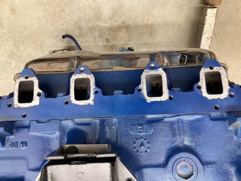
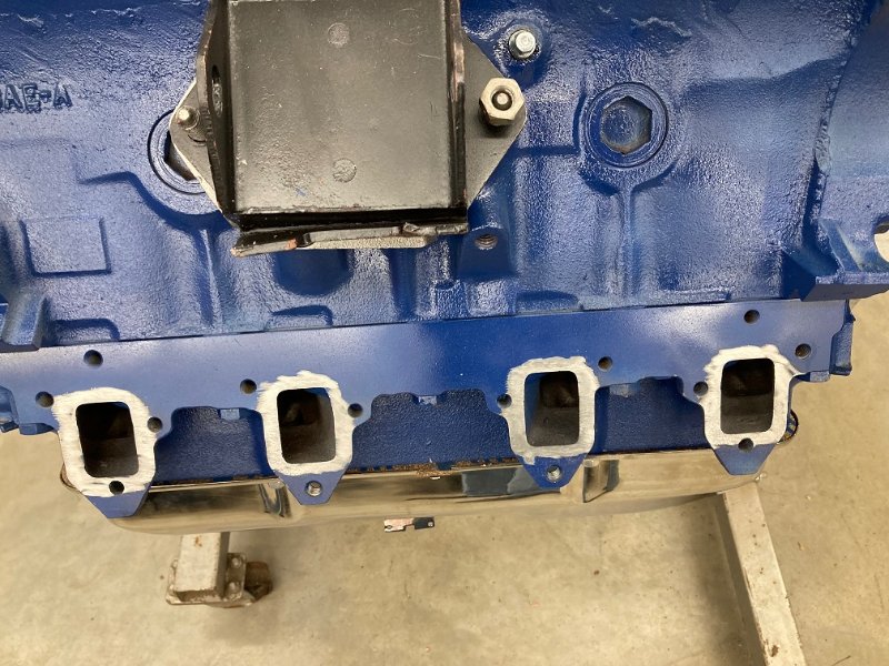
Exhaust manifolds came next. I cleaned off the blue paint on the cylinder heads to ensure a good seal. I used Super Blue RTV.
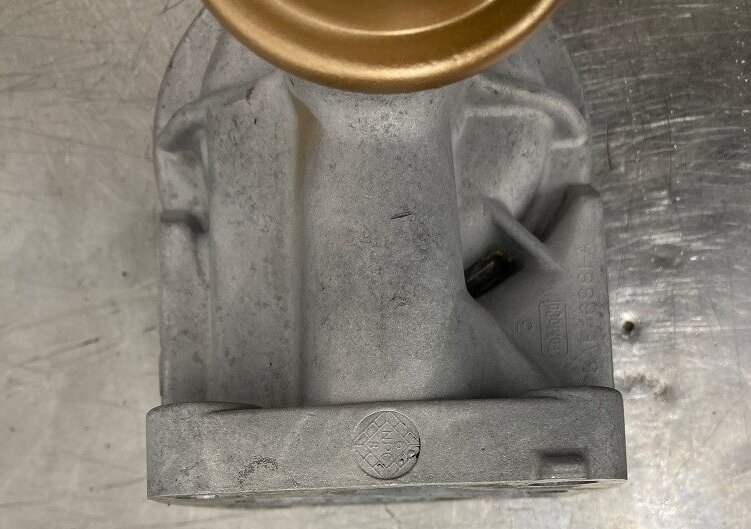
This car continues to amaze me as to the original parts it has. The date code on the oil filter adapter is February 1968.
Nice to still have the original parts to restore! I also refinished my old coil. I figured the wax inside might be dried up and cracked, which could cause internal high voltage arcing. But it seems to work fine.
Looks like cracks in the one head under the 8B2. Are they just casting imperfections?
Well I sure hope so. That would be a very expensive head to try and replace. Will find out if it holds water pretty soon.
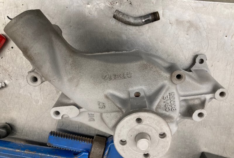
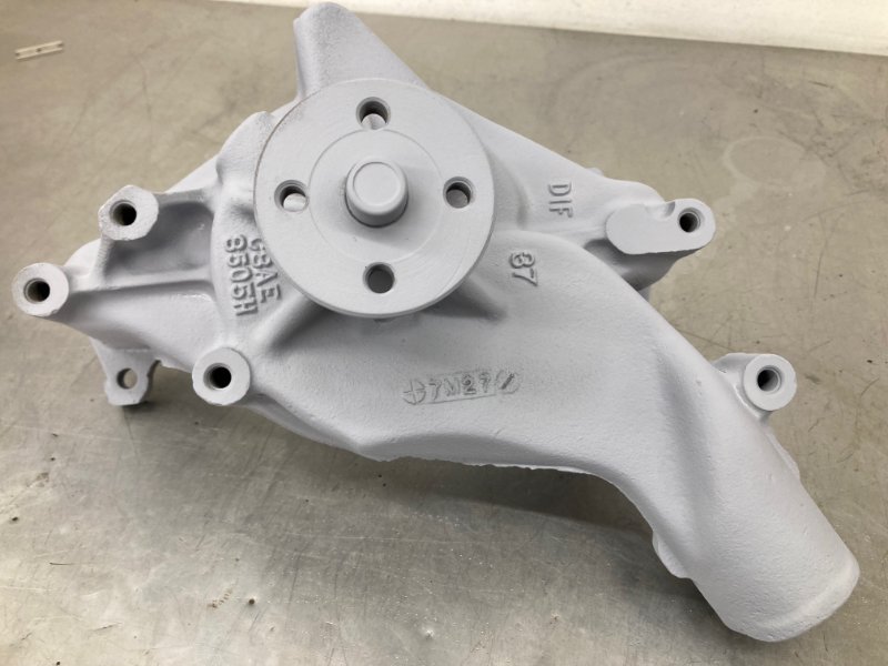
Working on the original water pump today. I ordered a rebuild kit from Dead Nuts On. If you have a hydraulic press it’s a simple job to rebuild one.
The heater hose nipple on the pump was giving me plenty of trouble. Someone had bent it nearly 90 degrees in the past and so it had to be replaced even though it was the original one. Lots of various sized wrenches, vice grips and channel locks didn’t touch it, combined with various penetrating oils.
Finally the 36" long pipe wrench got it loose so it could go in the trash can. I bead blasted it then primed it so it would not rust again.
Worked on the steering column bracket which also provides a mount for the brake pedal and booster. The assembly looks a lot better than it did this morning.
Pictures don’t want to be included…
From the gallery.


This car came with a lot of its original parts including the fuel pump. The original W and R code fuel pumps are a 4441S Carter pump that is easily rebuildable - if you know how. It’s a fairly complex process. I tried to document all the steps so that you won’t have to learn like I did.


The first step in disassembly is to remove the #10-32 screws securing the pump section to the check valve section. Set the check valve section off to the side for now and clamp the other part in the vice so you can remove the spring from the pump arm. It will fly across the shop and be lost permanently if your technique is bad.

With the spring out of the way you can remove the spring seat.

There is an aluminum cap covering a hole in the side of the pump where the axle for the arm lives. You have to first bend back the aluminum tabs that secure the cap. Normally they just break off. If you are super careful one of them might survive. Mine broke off.

Once the tabs are gone the cap can be pried out with a flat blade screw driver.

Once the cap is off the axle can be manipulated to make it move out from the pump body.

Once you have a 1/4" of the axle protruding you can grab it with pliers and remove it.

Then the pump arm can be removed.
With the pump arm removed the diaphragm assembly comes right out. The pump section is now disassembled.

We start disassembly of the check valve section by removing the two screws that secure the inlet housing to the valve body.

This is a high performance pump, so it has two check valves on the inlet side and one on the outlet side.

The check valves are removed by punching out the center with a 1/8" diameter punch and a hammer. The work bench provides a flat surface.
