There is a rubber plug / grommet that takes the hoses through the firewall. That, and the original headlamp hoses, were in excellent condition on this car with only clean up required. I cleaned the hoses in isopropyl alcohol which did not affect the stripes at all. With the switch laying on the floor of the car it is very easy to install these hoses.

The connector is snapped to the switch, the “Headlight” ring is installed, and the center shaft holds everything to the dash. I tightened the shaft with a #4 Phillips screwdriver.

The ignition switch is installed next. WCCC sells a special tool to tighten the chrome nut. It’s pretty clumsy to use but gets the job done. I am going to weld a piece of an old socket to it to make it more user friendly in the near future.

This batch of items is going in place to make it possible to install the firewall insulation pad, and the engine / transmission which are currently taking up a lot of shop space.
The brake line to the Right Front is installed next. It’s possible to install this with the engine in place but far easier to install now.
It would be interesting to see if we have enough data in these threads to determine the order of assembly as done by the factory. Imagine a check list that told you exactly what to do next.
Good idea but it would take lots of work Bill. However it would likely save a lot of folks a lot of work too.
Don’t forget to install the throttle pedal before the engine.
Yes it’s coming right after the firewall insulation pad.
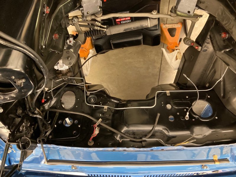
Temporarily stopped on the firewall pad - I needed to make sure all the holes were in the firewall, one being the hole for the tilt - away hose. Then I looked at the passenger fender apron and it had been patched masterfully so as to remove any trace of rust - and they didn’t make any holes for the tilt - away vacuum cannister. So I set about measuring the one from the car - it tested good with a vacuum pump.
The mounting studs were about 3 1/16" center to center. They are 1/4" - 20 bolts. The center grommet measures 1 1/2" where the original fender depression was so I copied that.
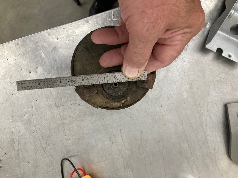
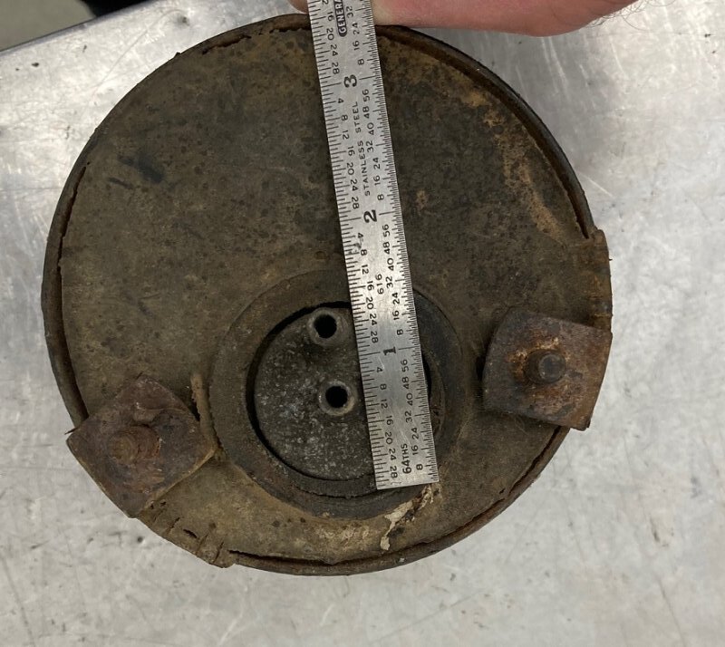
This picture shows the distance off the frame rail to the center line of the holes. It is about 4 1/4".

The finished product. I capped the fittings and bead blasted the outside of the tank lightly. The stamped sheet metal nuts are the original ones.

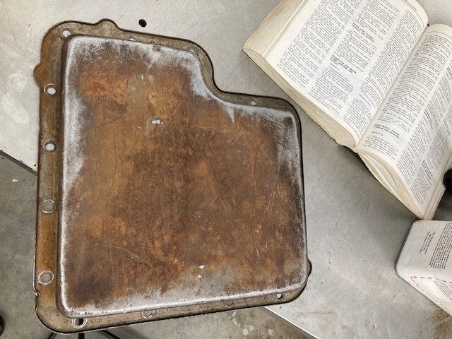
With the firewall mostly done I started getting ready for the engine / transmission installation. Looking at the freshly rebuilt transmission the pan looked out of place with all its surface rust. I bead blasted it and painted it with cast blast.
The car got rolled outside so I could turn it around this afternoon. The nose high stance will be gone soon.

First thing today I installed the transmission. The torque converter has one quart of Type F in it already.

With the engine dangling from the hoist it was time to install a few things. The starter gear flex plate / flywheel is indexed so that it can only fit one way in order that the engine is balanced properly. I start by finding out where the doubler ring fits the crankshaft. Then I make a mark at the top for ease of installation.

Then I laid the doubler plate on the flywheel and made a mark in the same “up” place. This makes it really easy to assemble.

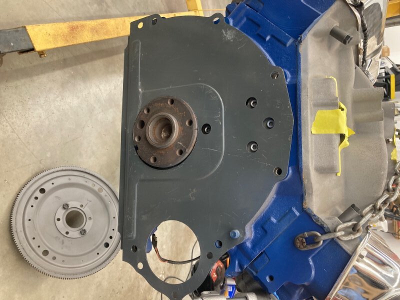
Then the flex plate and doubler are installed. Each bolt gets a drop of Loctite before it is screwed in.

The flex plate is locked in place with a screwdriver (not shown) stuck in one of the bolt holes so it contacts the block so the plate can’t rotate. Then the bolts are torqued to spec.

With all the preparation the engine installation went smoothly today. It’s in place and bolted down. What is left? Nearly everything…
