What is the deal with the intake? Looks like plastic?
How to install a Pertronix Ignitor and not cut any wires and still use the factory tach.
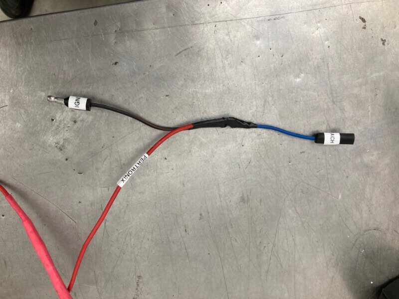
I crimped a bullet male end on the Pertronics red wire. Meanwhile I made this adapter harness using a female bullet connector, a male bullet connector, and a 30" long piecce of red #16 wire with another female bullet connector. All threee wires are soldered together and labeled where they go.
The Pertronix Ignitor has two wires, one black and one red. The black wire connects to the coil using the factory elbow connector. I spliced the factory black wire to the Pertronix black wire. The factory yellow top coil is used so the tachometer is still accurate. The + side of the coil is the wire that is existing.
The Red Pertronix wire has a male bullet connector crimped onto it. That plugs into our adapter harness which I ran through the existing tilt - away vacuum hose grommet.


This is the view inside the car with the new harness plugged into the wire that supplies 12 volts to the tach. The second wire that is connected to the tach is the male connection which is the existing pink resistance wire that leads to the firewall. Then it connects to the coil +.

This is the schematic that comes in the box. It leaves out the factory tach and resistance wire - we need those.

Among other items I rebuilt the original water pump today.
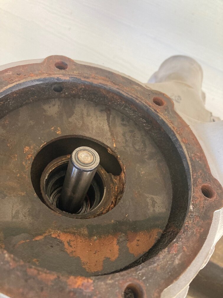
The rear cover was very rusty inside. I threw it and the bolts away. The water pump got bead blasted earlier, then primed.
Then used an old bolt to press out the bearing / shaft assembly:
The water pump rebuild kit from Dead Nuts On includes gaskets, a new shaft seal, and the shaft / bearing assembly. I purchased a new fan pulley flange which is an available extra. You could re - use your old one if it is in good shape. This one was rust pitted.

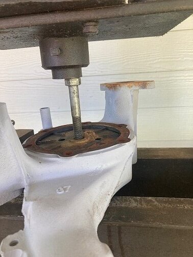
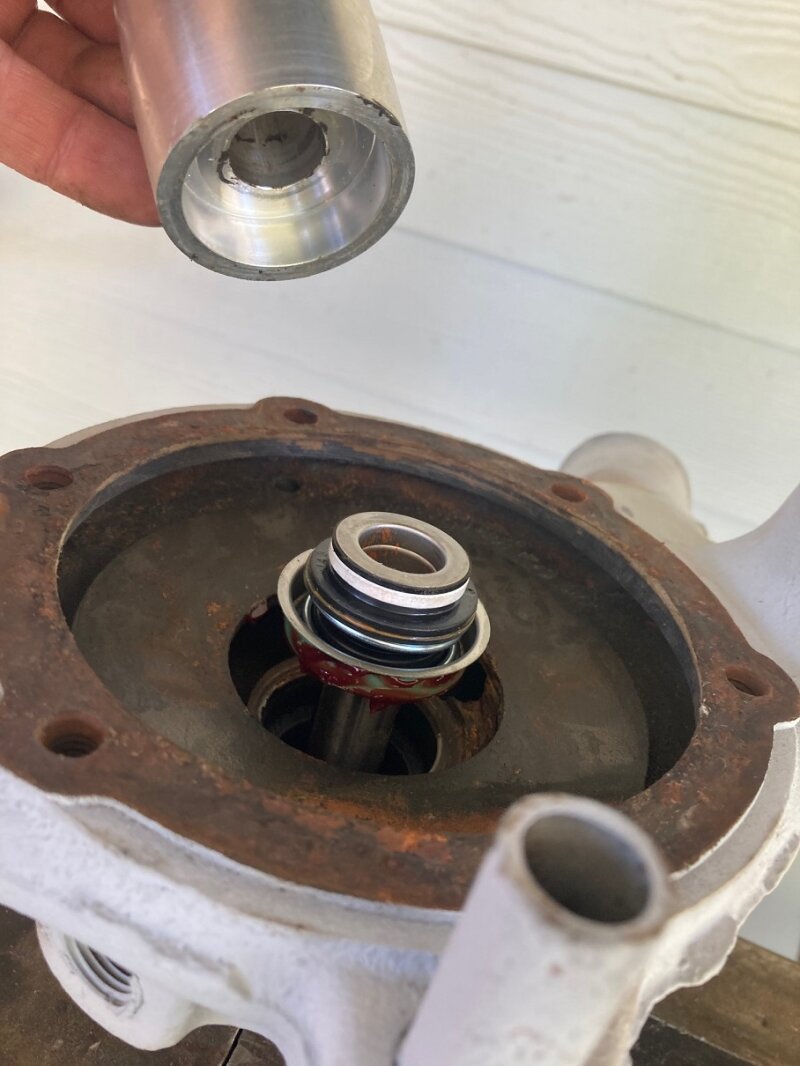
DNO also sells this nifty tool that is used to install the bearing / shaft assembly and also the shaft seal. I used it along with the hydraulic press to install the new bearing and shaft. The long shaft goes into the pump, the shorter shaft is in the DNO tool.

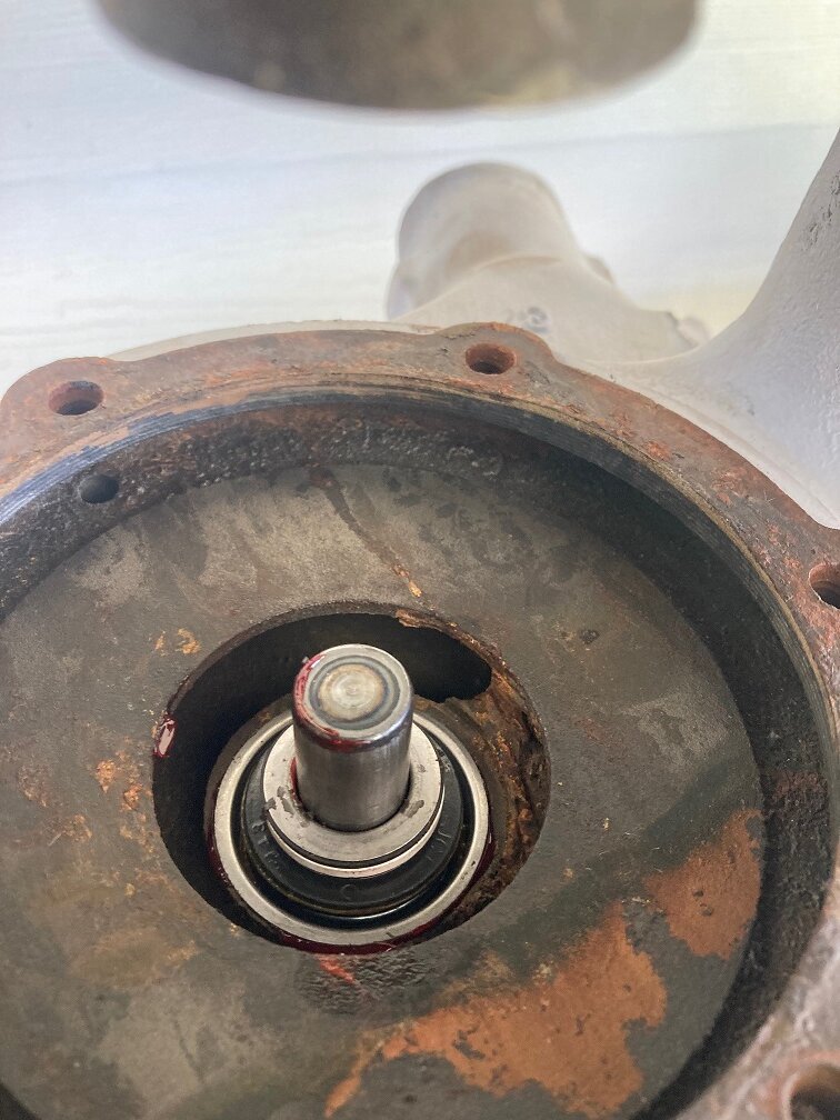
Here’s how the shaft looks when seated fully. The bearing face is flush with the casting. Note that I put grease all over the bearing before pressing it in. I wiped off the grease before taking this picture.

Here’s the other side at the same moment in time. I knocked the old seal out with a hammer and a deep socket, then carefully cleaned the area where the seal is installed before pressing the new shaft / bearing in place.
I put grease on the inside and outside of the seal before pressing it into place using the DNO tool again, this time with the recessed area towards the seal. The last picture shows the seal pressed into place after I wiped the grease off.

The impeller is pressed on next. DNO sells a stamped steel impeller, it is nowhere near as well designed or effective as the stock one. You want to use the stock one if it is in decent shape. It gets pressed on until the rear of the impeller is just clear of the rear of the water pump. Yes, grease all over the shaft before pressing the impeller on.

Next the pump is flipped over and the fan pulley flange is pressed on after it gets greased. Use the original one to find the dimension required. Again the DNO tool comes in handy. The bottom of the shaft is supported off camera.

A new cover and bolts also came from DNO. After they were installed the whole thing was wiped down with wax & grease remover and painted Ford Corporate Dark Blue.

Nice job on the waterpump Royce. Is the outlet tube going to the intake cast iron as well?
No it is a steel tube. DNO or Bill at Mansfield sells new ones if you need to change that part.
Very nice water pump rebuild tutorial !!
Thanks Jeff.
This needs to be subtitled “Things that should be done before installing the engine”.
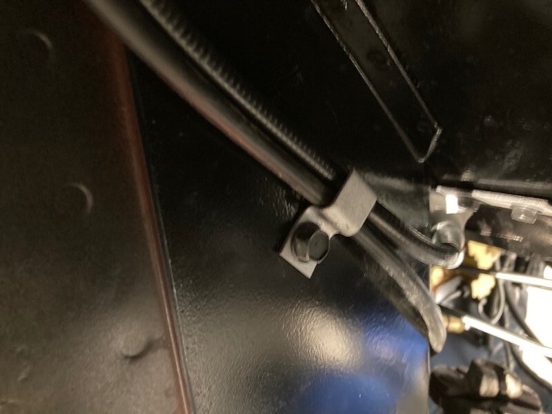
The parking brake cable has a clamp near the firewall with two self tapping screws attaching it. Then the parking brake cable and the speedometer are held to the forward frame rail with the dual clamp and a 5/16 - 18 bolt tapped into the frame. The lower one is OK, the one near the firewall is far easier before the engine is in place.