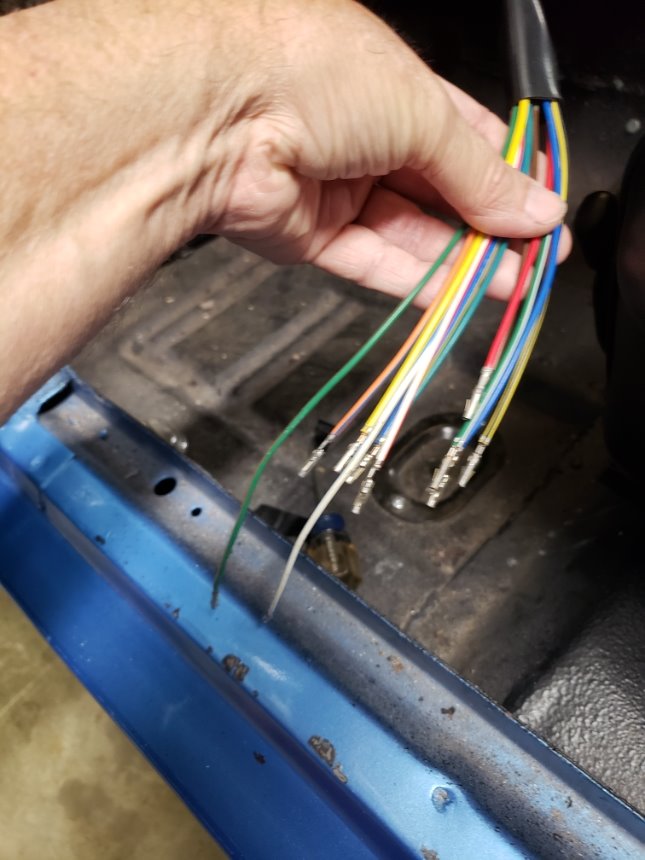
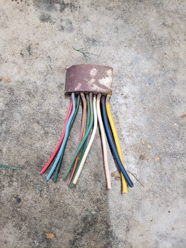
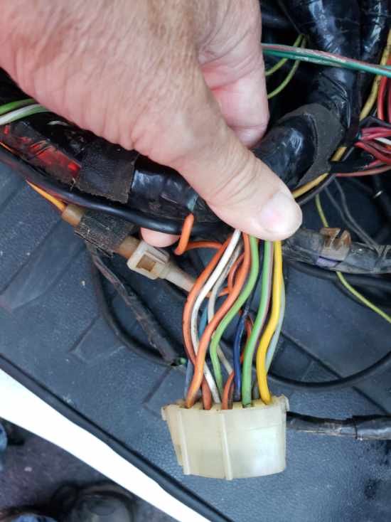
I purchased the 11062 turn signal switch for my 1968 cougar base non-tilt along with the 10686 plug from WCCC. Some of the wires are different colors. Could someone please help me determine the proper locations for each wire? I’ve attached photos of new switch wiring, old switch wiring and the where it attaches to the dash wiring. Your help is gratefully appreciated
Check out Vic Yarberry’s Cougar’s Unlimited website (http://www.thuntek.net/cougars_unlimited/). He is the expert on our sequential signal system. Not only does he have a troubleshooting section, here is a link to how the 67 and 68 turn signal wiring is supposed to go (http://www.thuntek.net/cougars_unlimited/1967-68_TS_Connectors.PDF). You can also match up the wiring from the old plug that you cut off and wire the new switch to your new plug. Also keep in mind that there are two wires that are not used for Cougars on your new switch (for T-Bird, or whatever).
Good luck.
The service replacement switch fits a variety of applications. There are two wires on the new switch that are not used in a Mustang / Cougar application. All of the rest match the factory colors. The schematic is in the back of your copy of the factory shop manual.
1 Like
Thanks Royce. I have been looking at that, however the old switch had a couple of wires in different locations on the connector. Just want to be sure. I am also puzzled that 2 of the wires on the new switch are longer and they happen to be 2 of the wires that are used.
Be sure that you have the orientation of the plug correct. There are indentations at both ends of the plug that, when plugged into the wiring harness end, clip and hold it together. You would have had to squeeze the harness end to release the end to the column. Like the old saying “measure twice, cut once”. In this case you want to make sure you have the plug orientation correct before you put the wires into the plug, as it is a real pain to get the wires back out of the plug if you don’t have the proper tool (sometimes even with the proper tool).
Good luck.
Thanks fordnutz! Great info. Any idea why 2 of the wires are longer?
Just ignore that and put the wires where they go. I use a connector removal tool but of course a piece of properly sized brass tubing works great too. If you want you can splice all the wires but that is bulky and unsightly.
I’ve tried most of the pin extraction tools out there, and I prefer my home-made version. Take a small jeweler’s flat-heat screwdriver and grind down one side to the middle of the shaft and be flat on one end. I use the tip to push in the locking tab for both male and female pins.
You are welcome. No idea why two of the wires are longer than the rest. You can’t really see them when it is together and plugged in.
Thanks guys!