Let me start by saying i removed my dash and gauge cluster 5 years ago shortly after I brought my Cat home, Most things seemed to work but there were some small issues i didn’t pay much attention to at the time. I rebuilt the gauges and lenses etc. and put them away. Most of the wiring was unmolested and in original form with tape tags and their original place which is a blessing after hearing and seeing some peoples bird nests,
I know very little about electrical issues but am trying to learn and figure it out with the resources i have. This Section is just relating to the dash.
Now, i have figured out 95% of my wires for replacing my gauge cluster and toggle switches etc as I have a 68 XR7.
I have spent countless hours studying my Electrical Assembly Manual to try to answer my own question so that by the time i got to this point they can be few and specific, so here goes.
i have a few colored connectors that i believe might be there for options my car does not have but i need input/validation on those.
The first is YELLOW 3 hole connector that is wired directly to the fuse box, Some of my research shows it may be for a rear defogger that i don’t have. Is that correct?
There is are RED 3 hole connector under the wiper motor with two red/blue wires. I assume these are for lamps but not sure what they go to as I may not have that option.
Also under the wiper motor, i have a GREEN/WHITE wire and a White wire connected together with I think non Ford connector that merges them into one wire of Green/White. Looks like might be left from the after market 80’s stereo I pulled out. Need to know what they are supposed to be used for.
Lastly i have 3 wires coming out of the steering column that presently are not connected to anything. My guess is speed control option which i don’t have. The wire colors are: Blue/Gray or White, Brown, and Yellow/Brown.
Thank you for any help in identifying these as i have exhausted my resources,
I can answer question #1 without digging out a print. That 3 hole connector is an accesdorie tap…a power strip fir your car…if you will. There so you can add 12 v options
The second 3 hole connector with blue/red wires is an accessory tap for dash lamps.
The third issue sounds like a non-factory set-up; I can’t help you there.
The steering column wiring doesn’t sound familiar…
I believe the “third issue” is to do with the turn signal ( wiring ) harness.
You probably have a tilt / tilt-away column ? The turn signal switch and wiring is different for tilt vs. non-tilt column equipped cars.
If you have the tilt column then the switch & wiring harness ( C8SZ-13341-B ) has the three wires utilized in the speed control which is mounted on the end of the turn signal stalk. If my memory serves me correctly, they were red, white and purple. If yours are faded then perhaps the red is what you think is yellow-brown and the brown is the purple ?
If you don’t have the speed control RPO, then these wires are not used, and can safely be wrapped in electrical tape around the lower portion of the turn signal wiring harness bundle as it soon as it emerges from the bottom of the column.
Mercinary, thanks for your reply. I kind of suspected something like that as I saw that connector in a few different drawings with different things plugged into it. Nice to know we have that option available. Thanks much for confirming that Yellow connector for you.
1 down!
Midlife, thanks for the message. Glad to know that I wasn’t missing something and that Red connector is extra! Just wish that is shown and explained somewhere in the colored drawing and book I bought. Could have saved me hours.
2 down
Yes, that was an option I considered as that wire is Green/White stripe too. That wire is connected to the brake switch though in less it was somehow cut earlier in the run. Not sure why the PO would need or want to do that so have to dig deeper I guess as I can’t test that switch quite yet.
gah, I just typed out a reply and it disappeared! I think you meant to say #4. I spent a lot of time on trying to figure these three wires out. Since the diagrams for the speed control option had different color wires shown, I wasn’t sure it was that. Not sure why they are different colors but since I don’t have a tilt column or speed control I am going to do as you suggested and tape them up and tuck em away.
4 is down!
Still need #3 (Green/White stripe connected to White) to figure out then I am good for the Dash area.
I am going to try to post a pic of that tonight.
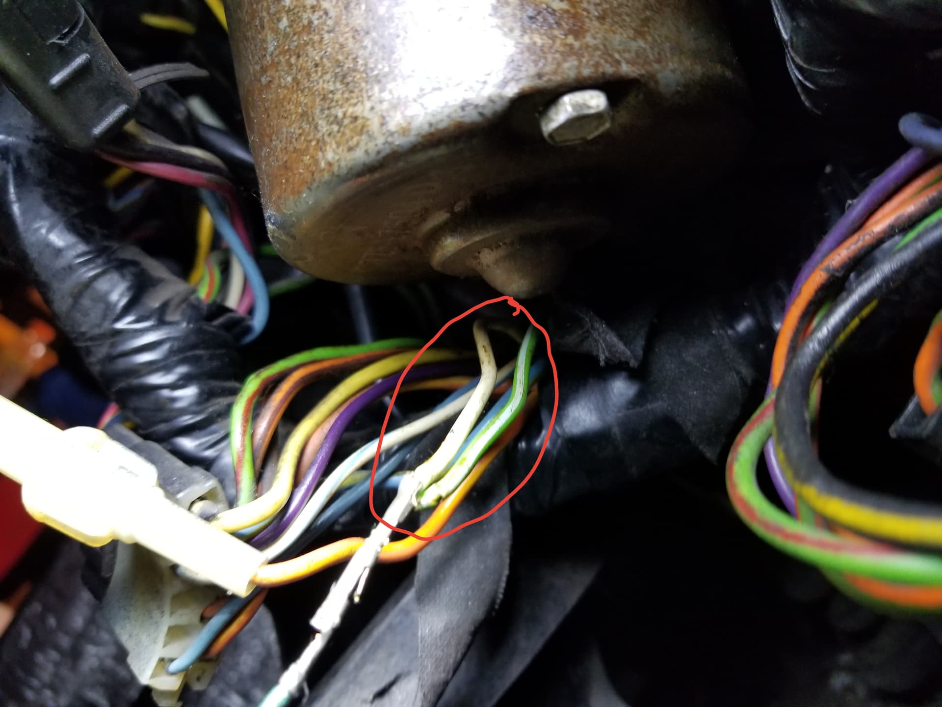
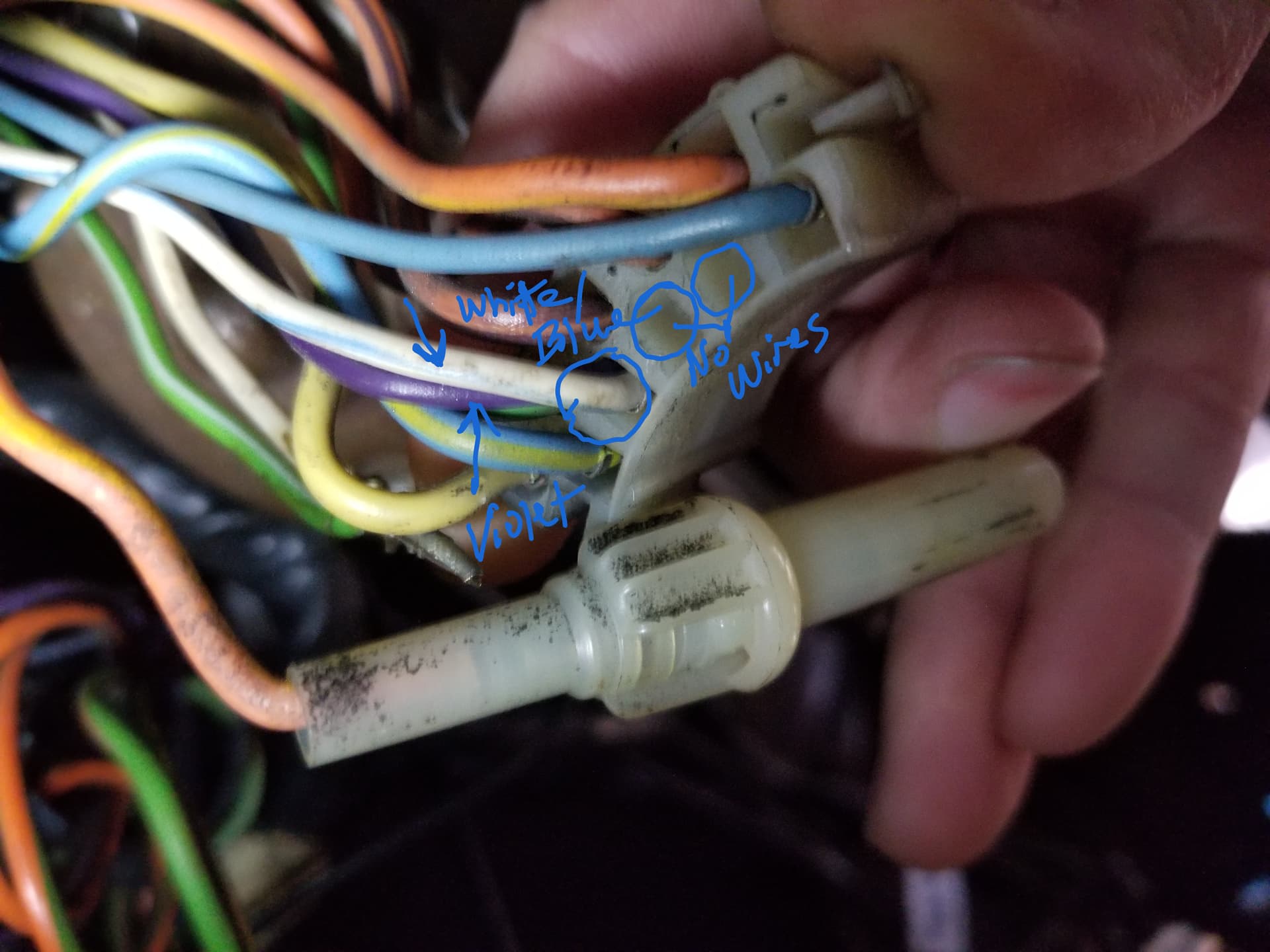
Here is a better view of where the wires originate which is right under the wiper motor and the same loom that all the wires that go to the steering column come from. There is no indication they were cut or don’t belong there. I still need to know what they are supposed to go to! I have the Green w)White stripe wire at my break light switch which is a larger guage than this one.
This is my last and only wire mystery left under my dash.
That kludge is the kind of thing used to work around a failed turn signal switch connector pin.
The 18 ga green/white (3) wire (left turn signal control from the turn signal switch) normally connects to the white (440) wire going to the sequential relay in the trunk.
Perhaps, at some point in the past, the green/white or white wire pin on 10-pin turn signal switch connector failed and crimping them together was the quick fix. Replacement male/female pins are available to put it back together correctly.
I totally agree with you. I have been working on this a week to try to figure out and think I did when i read your post so I am giong to show how I got to my own conclusion that seems to line up with yours.
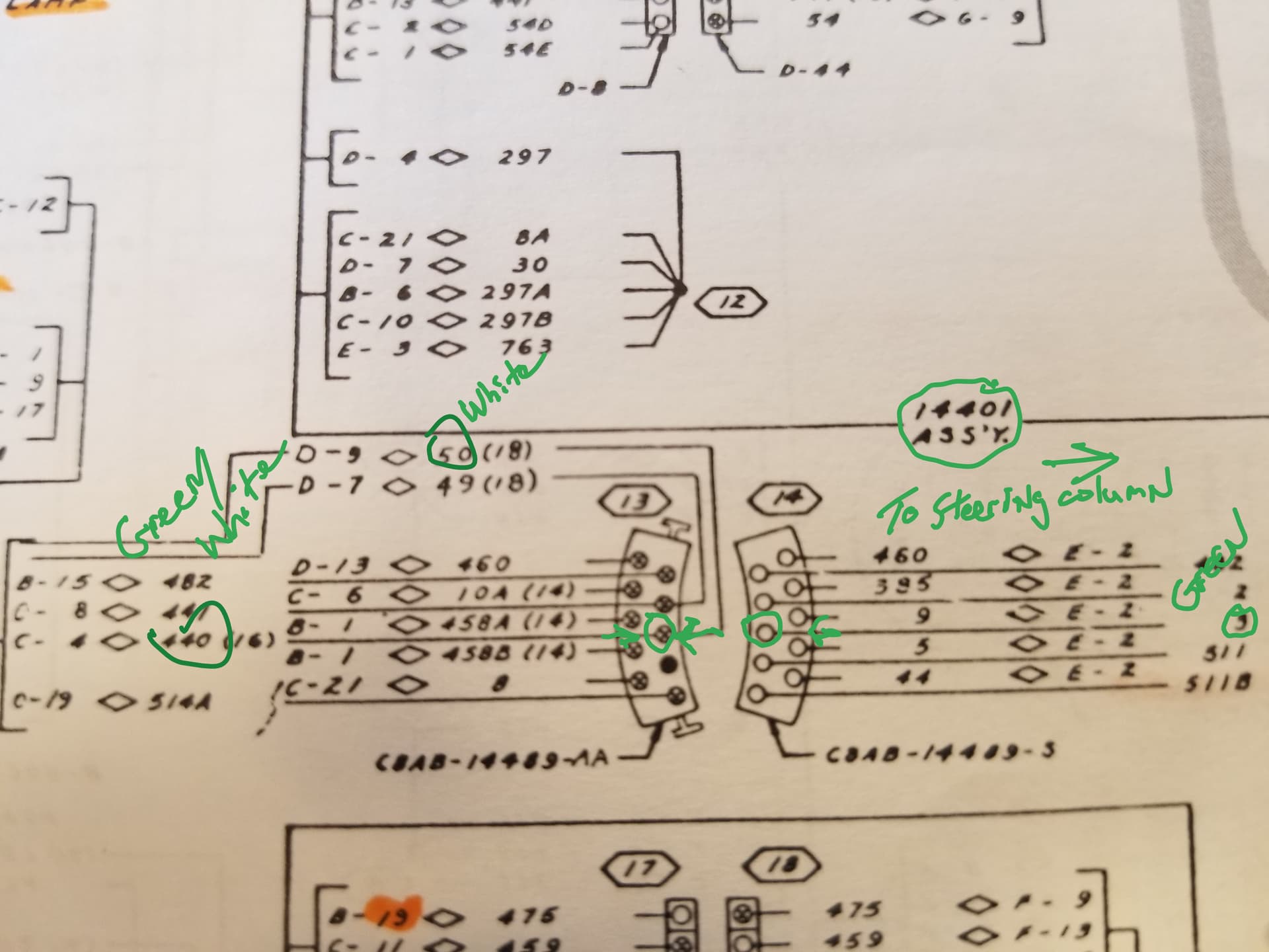
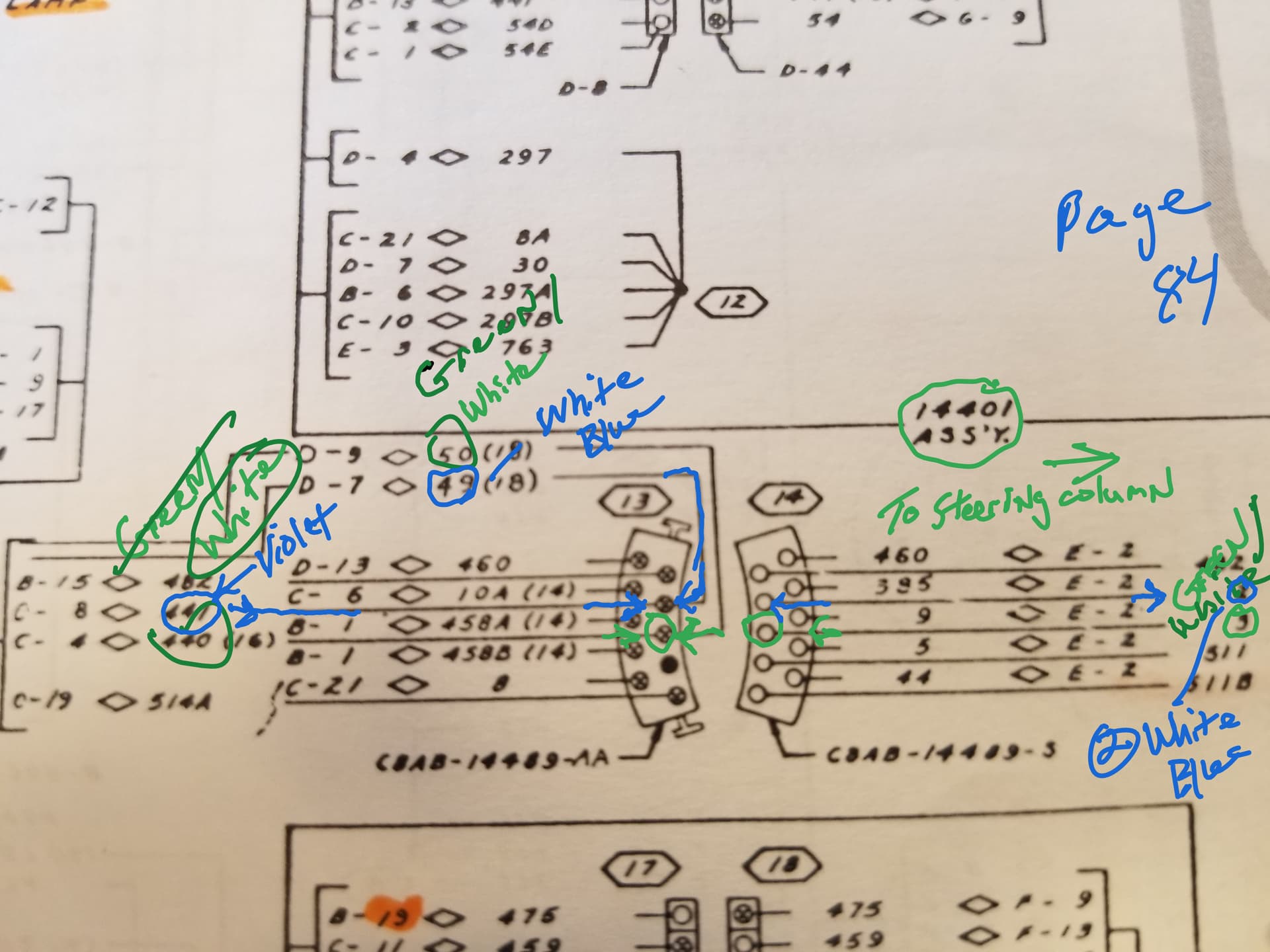
Here is the diagram for the turnsignal switch:
The left side shows a Green/White wire and a White wire in the connector on th middle hole on the right side. Across from that pin is a Green wire that goes to the emergency flasher switch.(Not shown here)
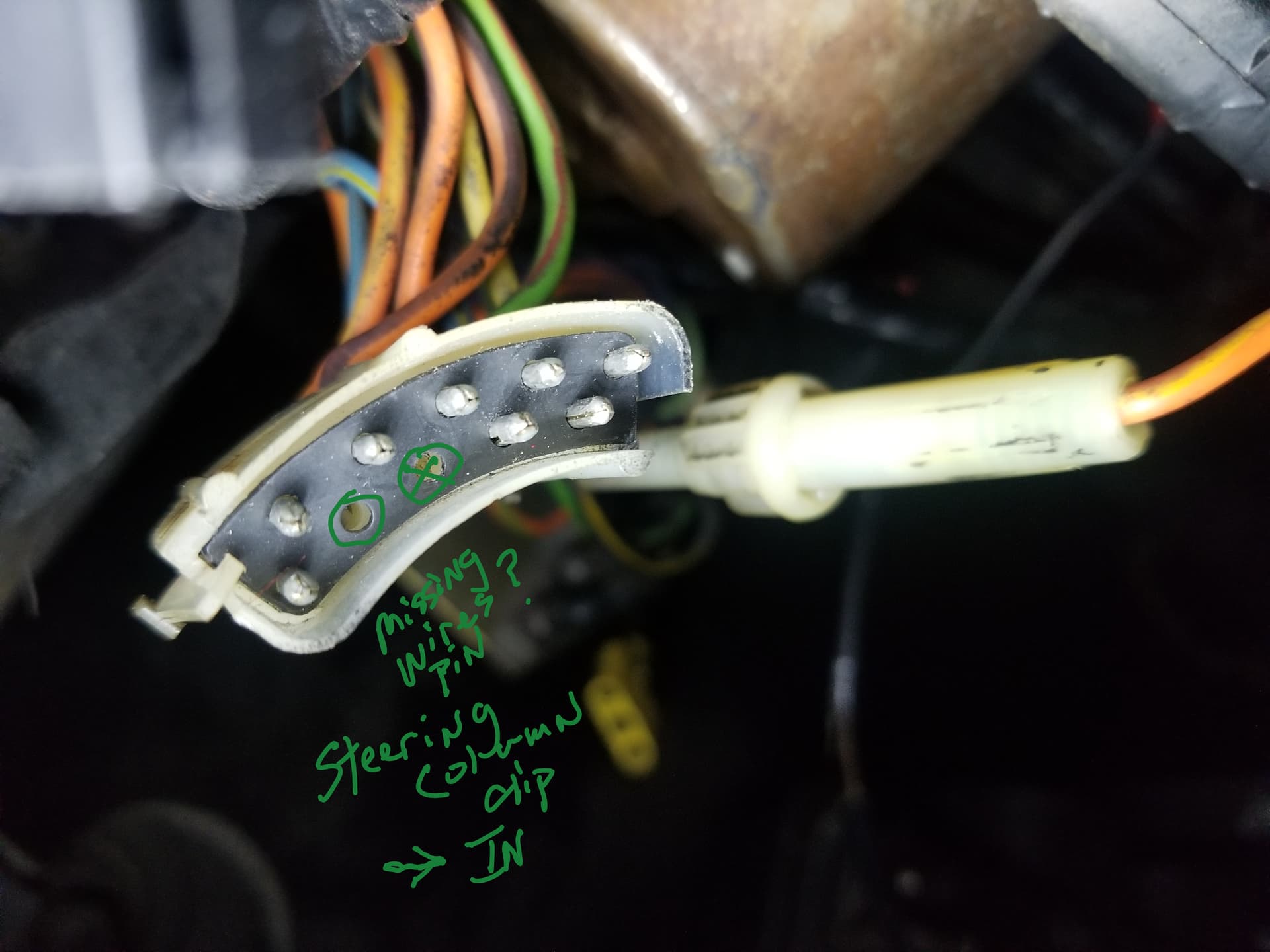
So looking at the connector going in > I noticed 2 holes without wires in them. The diagram above shows one blacked out (meaning no wire) so i am missing a wire/pin!
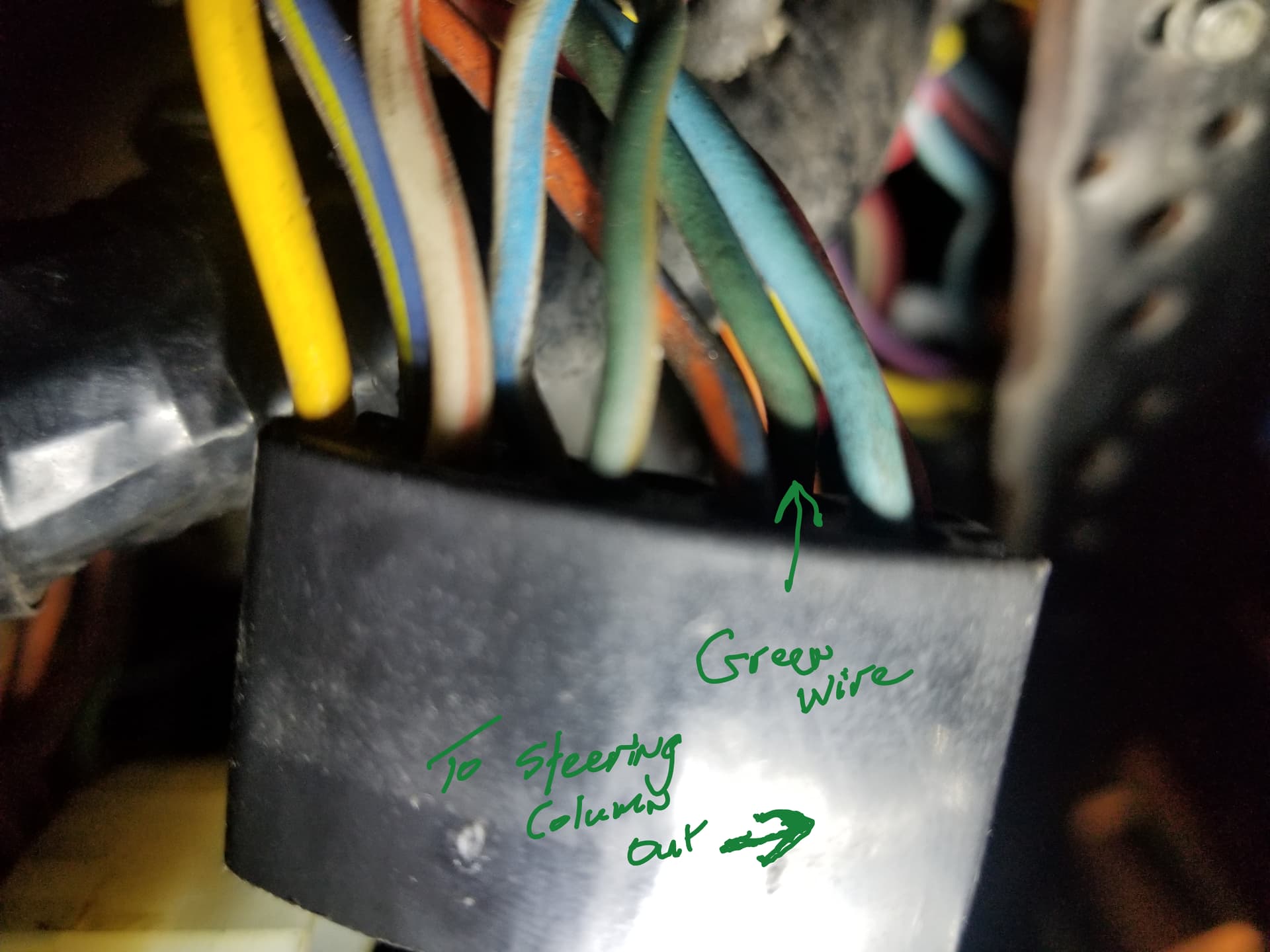
Those wires match up to the Green wire on the other half of the clip going out.
So to your point above, i just need to get a new pin and connect the mystery wires together and put them back in their rightful place!
And all should be well.
let me know your thoughts.
Excellent analysis!
The empty hole, on the car harness side, is the connection to the switched brake power input (green wire) - which is not used on a 1967-68 Cougar. The brake input is handled by the relay in the trunk.
No, the C8SZ switch extra two switch wires (brown, yellow/black) are used for the Thunderbird corner turning light option.
The cruise control wires are a separate harness.
I want to make sure I am understanding what you said.
So, I am correct in my assumption about the Green/White & White wire needing a new pin and put a back into the Connector?
On the diagram, it shows they should go in the center hole.
Is that part correct even though there is no wire on the other side of that connection?
Correct, a 1968 Cougar does not need or use the brown or yellow/black wires found on either the C8SZ-13341-A (non-tilt) or C8SZ-13341-B (tilt) turn signal switch.
These wires are only used on 1968 Thunderbirds with the cornering light option.
Perfect, thanks on that.
What about my question on the Green/White & White wire connection? Do they need a new pin or can I just stick it back in the connector with what is on there now?
A couple of corrections to your posted diagram - the color labels are swapped for the (50) and (440) wires.
The male pin (car harness side) should have a green/white (50) and a white (440) wire. Typically, these are crimped into the same pin. The (50) green/white feeds the LH indicator light in the dash.
The female pin (switch side) has a (3) green/white only. It fits into the hole where you have marked with an X.
I cannot tell from your pictures which green/white wire is connected to the white wire.
Both the (50) and (3) wires must be located.
Also, the diagram shows #50 is Green/white on the color chart.
White/Blue as #49 which is joined with #441 Violet on the connection.
On the female side i show they line up with #2 white/blue
These i got off page 84 which color chart is on page 85.
Show me where there is this #50 White/Blue wire please as i only see Green/White as #50, Although it can also be (#3,#448,#475 too)
I just want to understand your intrepretation better and be on the same page as i really value you opinion!