I am not sure how power would have been feeding back up to the dash as I used the existing ground on the bolt on the housing. Is a ground that I found worked best on my tests but I am a newbie to this so what do I know.
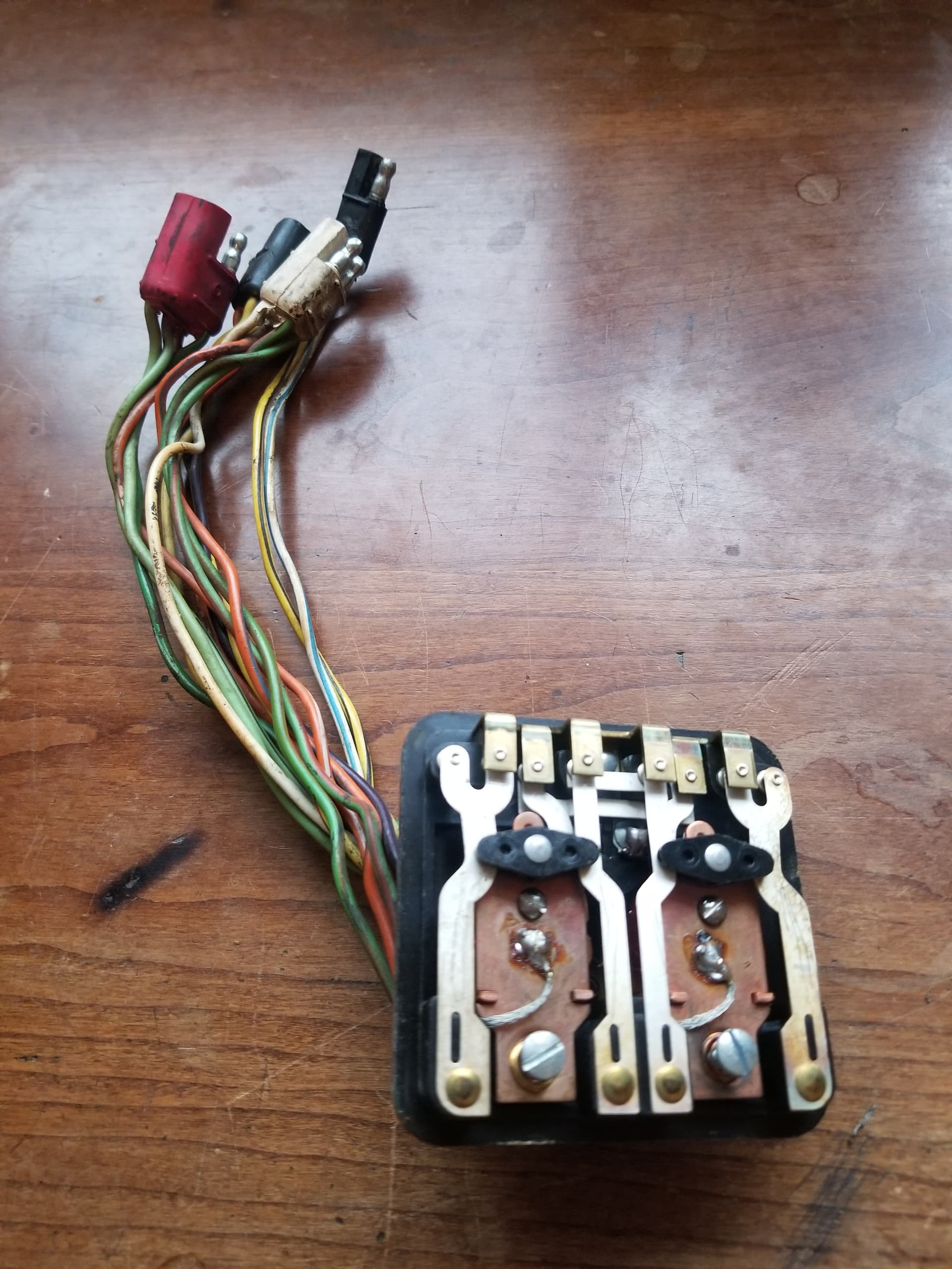
Another first for me here moving the solder just expose the prong used for the ground connection on the K8/K9. So I have it open now and don’t see any visible corrosion or damage. Will a small piece of sandpaper of a fine grit work to clean the contacts? Or do I need to order the special tool you mentioned earlier?
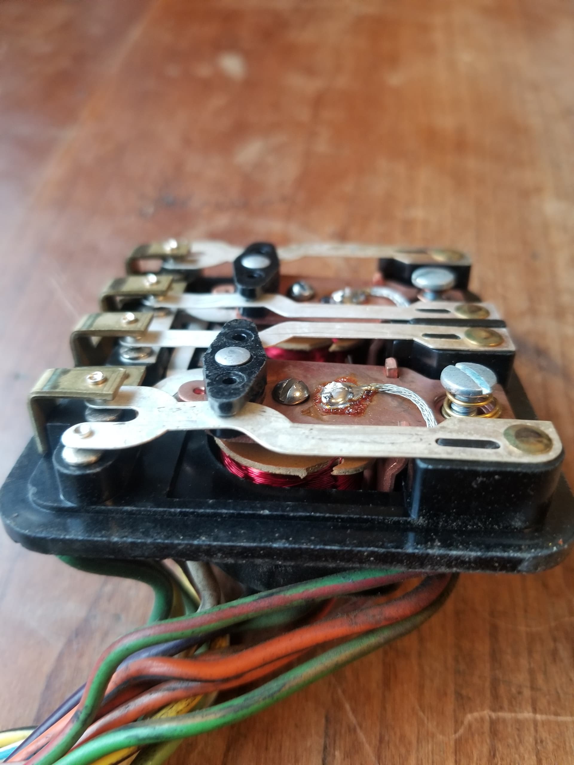
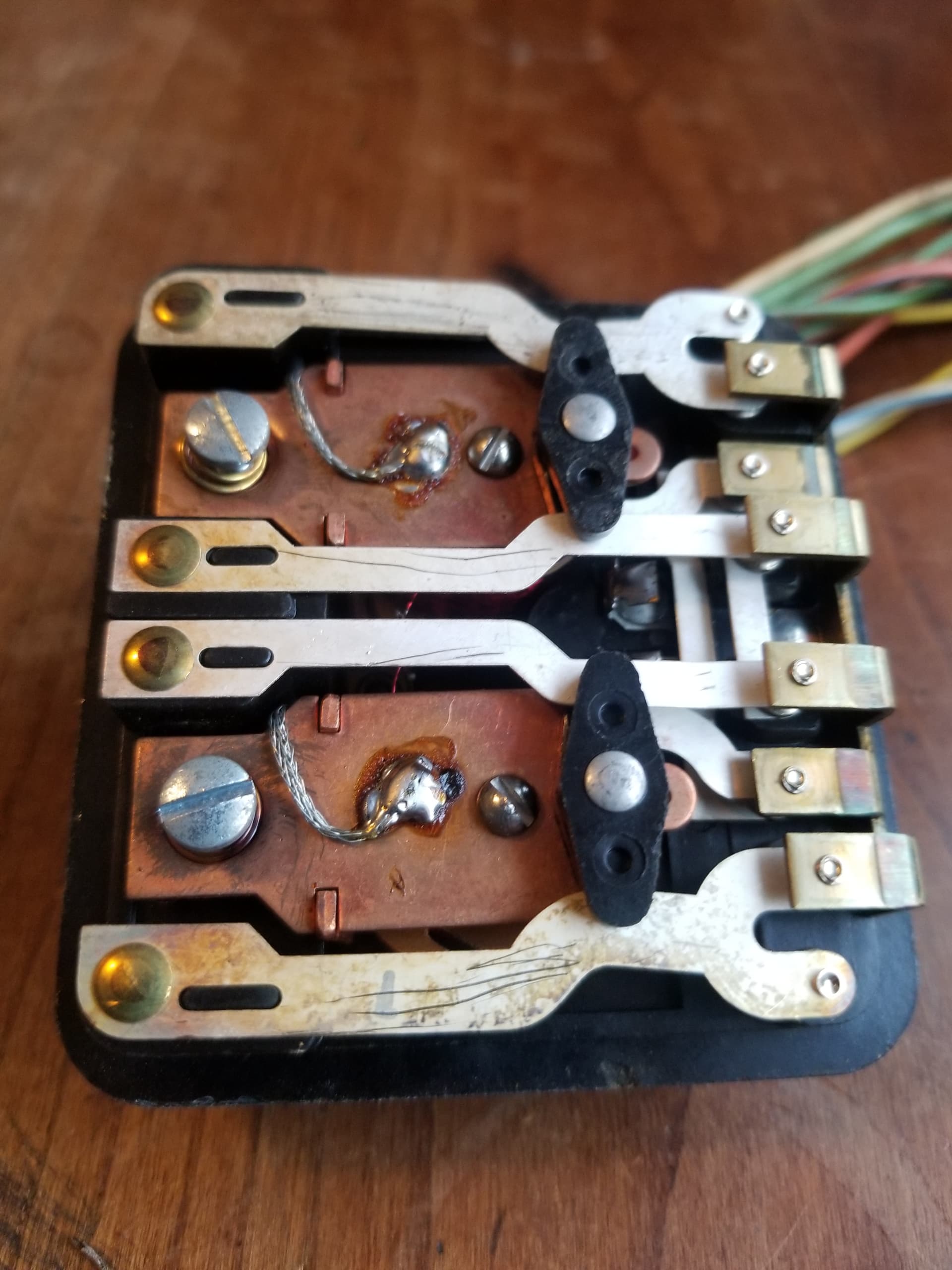
The reason for using the recommended tool is to avoid removing the thin plating that protects the relay contacts.
2000 grit sandpaper can also be used.
You can operate and test the relay out of the case by applying 12V to either the violet or white, and grounding the brass tab. Then use an ohm meter to the resistance through the contacts.
Got it. I have ordered the tool so I can try to do this correctly.
In the meantime I will test the relay again and contact resistance.
Quick question on testing the resistance. I apply the 12v to the White or Violet (I get) then am I testing between the three wires (yellow, yellow/red & yellow/black) and their respective contacts on the inside? And these should be less than .1ohms, correct?
Thanks!
Do you have a copy of the Cougar Turn Signal and Emergency Flasher Systems manuals?
A version of the 1967 manual is down-loadable from West Coast Classic Cougar at no charge.
The 55 page 1967 manual is the most complete and shows the signal path (in color) from the turn signal switch, through the sequential flasher, emergency relay, the main turn signal relay out to each of the lights. Except for the indicator relay, the signal paths (and wire colors) are the same for the 1968 Cougar. Be aware that there are several errors in the schematics of these factory manuals but the signal path diagram information is correct.
Use the manual to trace how the yellow, yellow/red, and yellow/black signals feed through the main relay. Then use your VOM to measure the resistance from each input pin to each output pin when each side is activated.
Right (violet)
inner lamp: yellow → orange/blue
center lamp: yellow/red → orange/white
outer lamp: yellow/black → orange/red
front : yellow/red → white/blue
Left (white)
inner lamp: yellow → green/orange
center lamp: yellow/red → green/red
outer lamp: yellow/black → green/black
front: yellow/red → green/white
Emergency flashers activate both sides of the relay simultaneously but drop out the inner and outer lights on both sides so that only the center and front lights flash.
I am not familiar with that manual. I know the free downloads from WCCC and only have seen the complete electrical schematic for 67 or for 68. Is it somewhere else on the site I am missing besides Free Resources?
I appreciate the guidance on color of wires as I have been spending so much time on this I am starting to learn them and think I can do it with these tips but still want that resource as I am very visual in my learning style!
I looked and I no longer see it listed. ![]()
I have a corrected version that includes both the 1967 and 1968 manuals on CD available for sale.
Heres the link to the Factory Manual on the WCCC web site
You should also download my pdf writeup as well
Coach Jack
Coach Jack, You must have super secret access as neither Vic or myself could locate it. I also called WCCC and they couldn’t find it.
I will get that ordered and on my laptop so I can use for reference to get back on track with trying to get my turn signals working.
I did have your paper and have read it several times and appreciate your contribution to this topic.
I was able to download the one Coach Jack sent but know it is only for 67 so I would be interested in getting your updated version for 68. Can you send me a PM with a link or how to get that please?
I wanted to provide an update on status for this thread. I have been working on my sequential lights issue now for a few months.
CougarsUnlimited.net has been a huge help with this issue and very good to work with me. We have done much
trouble shooting and testing. I finally determined that my sequential flasher unit is not working despite all the efforts to get it to work.
That said, I reached my patience limits on this and made the decision to purchase the Solid State box from WCCC.
I received that yesterday and plugged it in today and was overjoyed to see my tail lights working properly! Emergency flashers worked, front turn light worked, dash indicator lights worked, and the new solid state turn signal indicator was clicking!
I put a lot of time and effort to keep it original but at the end of the day I just need them working correctly and I don’t feel too bad I couldn’t do it. To me the money was well worth it to know they will now work for however the car lasts and I am at peace with that.
Just closing the loop on this one.
On to the next project…
Thanks for taking the time to tell us how you solved the problem.
I too prefer to rebuild original parts when possible. But when it’s not possible it’s helpful to learn about replacements that work.
Thanks for the post. This is one I regret the amount of time and energy I spent trying to keep original. I feel the same but this new tech on an old part is well worth not having to worry about when it will fail, well worth the money!