Here is a summary of several months worth of installation phases and problem resolution:
EFI and electronic ignition conversion on a 1970 Cougar XR7 351C-4V w A/C
Phase 1 install Holley Sniper EFI (#550-870) w/ Holley OEM In-tank fuel pump (12-305) replacing a Holley 4160 carburetor.
Phase 2 install MSD EFI 6 Ignition (MSD-6415) with Holley Dual Sync Distributor (565-111) with timing control. The ignition upgrade followed after the fuel side prove out.
Installation Summary
Phase 1 of the EFI installation. This has not been simply assembling purchased components.
O2 Sensor
Started with adding the O2 sensor bung which was not easy. Had to cut and pull the welded exhaust to remove the H pipe to install the bung. I probably could have pulled the master cylinder and brake booster and come in from the top instead, but that didn’t seem easy either and would have had access issues. The Holley instructions and video say do not install in the lower half of the pipe, keep it 10 degrees or more above horizontal. Cut hole and used a clamp on bung 90 degrees above horizontal. Reinstalled pipe and later was advised by Holley tech support that straight vertical was not good. It has a condensation and corrosion issue for the probe. It’s staying like that for now. I did need to buy the kit for the 2-1/4-inch pipe (a 2-1/2 inch one that comes with it). I purchase a weld in bung but found it was stainless steel and I am not set up to weld stainless nor was I patient enough to wait to find a weld shop so I’m running the clamp on. Later I had a problem with the pipes sagging at the short U-bolted couplings. These were replaced longer heavy duty band clamp couplings by a muffler shop and the O2 sensor bung welded in while there.
Coolant Temperature Sensor
Next was the coolant temp sensor, it went in place of the existing one is on the block. A radiator hose adapter fitting was installed in the upper radiator hose just above the thermostat for the original temperature sending unit connected to the factory temperature gauge. This may only be used to let the EFI controller know that the engine has warmed up (>160F) and auto learn can be activated. I’m tempted to switch them back and let auto learn start after the thermostat opens. There is a pipe plug in the intake manifold in front of the throttle body and a bit to the right that may be an alternate temperature sensor location. I discovered it too late and it’s right under the fuel rail, so it remains unexplored.
Fuel Pump and Filter
Emptied the gas tank to install the in-tank pump in the factory opening. Ran the fuel pump power wiring from the trunk to the engine compartment. Removed and reinstalled the left rear interior panel, rear seat, door sill scuff plate, kick panel, instrument cluster and dash pad to run these wires.
Modified the Holley in-tank fuel pump assembly with a longer fuel float arm to allow the level sensor float to travel the full height of the gas tank (the 22 gal. tank’s 9-1/2” height has always been an issue with fuel level sensors). If you have reason to pull the tank, I recommend installing the fuel pump assembly with the tank out and inverted. I suggest using a high tack liquid gasket sealant to hold the seal ring in place while installing the pump. Doing it under the vehicle makes for challenges in keeping the sealing ring in place while assembling it. Upgraded all the fuel hose sections in the existing steel tubing line with new pressure rated hose. This fuel pump has a built-in pressure regulator so there is no return line. The fuel filter was mounted on the driver side of the engine compartment. I thought I was going to have to fabricate a mounting bracket until I realized that the filter is the same diameter as an ignition coil. An ignition coil bracket worked very well. Removed the original fuel pump from the engine and installed a blank off plate. Fuel hose was run across the top of the engine with ¾” heater hose used to protect it as potential rub points.
Note: Also, fabricated a new bracket to add the low fuel warning sensor (an XR7 standard item). Had to design it to still fit through the existing hole in the gas tank. I repurposed the redundant ground wire from the unit for the warning light signal output. Prior to installing it I was informed that the commonly supplied thermistor this for is the wrong resistance range and will not work well. This upgrade was deferred.
Throttle Body
Revised the fuel rail adding a 45-degree bend to bring the fuel connection to the front. The straight hose and fittings that Holley supplies do not clear the throttle position sensor when facing for a front connection. Added a pressure gauge on front, it was planned to go on fuel rail coming around the front of the throttle body but it doesn’t clear the distributor. It was relocated to the incoming hose. It will be more visible there anyway.
Note: the 315C-4V carburetor to manifold gasket has a sheet metal block off to the manifold heater passage, do not use the Holley suppled gasket. (Note: Failure to keep all of the original manifold gasket compressed and retained can result in gasket fragments from the areas between the venturis breaking loose and wedging the throttle plates open. – It happened to me; a stuck open throttle while driving is not good).
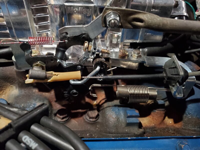
Linkages
Holley does not have a throttle cable and return spring bracket nor a A/T kickdown bracket. They refer you to Lokar Inc. who doesn’t have them either, unless perhaps you want to try converting to their full new cable sets. Neither of the old 4160 carburetor brackets will work. The throttle cable and return spring bracket (#20-151) for a Holley Terminator was modified to shorten it about a half inch at the mounting holes. Later the mounting holes were slotted about an 1/8th inch to allow better adjustment of full throttle opening and better actuation of the A/T kickdown. The Terminator A/T kickdown bracket (#20-152) works nicely for the spring attachment and provides a spring and hardware for the adjusting screw. Unfortunately, the kickdown linkage on the Holley throttle body is not long enough for the factory rod. An extension piece had to be fabricated. On power up the Throttle Position Indicator (TPI) was not showing full travel. The U nut/retainer provided with the A/T kickdown is very convenient for holding the adjusting screw but it interfered with the secondary venturi throttle linkage. A simple hex nut on each side worked better. The adjustment required closely watching and adjusting the kickdown rod and avoiding interference with the secondary venturi throttle linkage. Check the Ford Service Manual for instructions on the proper adjustment. Mis-adjustment either doesn’t activate the downshift or prevents full throttle opening. Recheck the TPI for full travel. This is when the bracket holes were slotted as mentioned above. The throttle bracket and throttle plate lever provide holes for return springs. I transferred the two return springs from my Holley 4160 carburetor but found this to be overkill. The two springs built into the throttle body shafts on the Sniper seem to be sufficient. There is no instruction to add any additional springs.
Wiring
The Touch screen cable was routed through the firewall with a new ¾” hole and grommets, a CAN bus extension cable (558-424) was purchased to move the connection for the Touch screen to the console. Unfortunately, the CAN bus extension cable from Holley does not have the correct connector gender for this purpose. It has two receptacle ends rather than one receptacle (female pins) and one plug end (male pins). I fabricated a short two plug end cable to make it work. It requires 20 or 22 gauge stranded wire. The connectors are Molex Mizu-P25TM 2.50mm pitch miniature waterproof connectors (available at Mouser.com). A PerTronix Quick Change Ratchet Crimper or other similar tool with a 22 ga. D-Sub die is needed to crimp the tiny pins, get some extras as some practice and sharp eye sight is needed. Fortunately, the really expensive crimper that Holley sells is not required. The ratchet crimper is a great tool for all of the connector crimps.
Mounted the Holley main harness with fuse and fuel pump relay on the passenger side of the firewall. Routed wiring along the firewall and the passenger side of the engine compartment, mostly attached to existing wiring. Coiled up extra harness length above the manifold, to the rear of the throttle body. It’s hidden fairly well by the air cleaner.
Ran the initial power-up with the Touch Screen calibration wizard. Sensor verification and startup were straight forward. Recruited a passenger ted to readjust (slightly bend) the throttle bracket to compensate. Otherwise, all went well.
Phase 2 - Ignition - MSD EFI 6 Ignition (MSD-6415) with Holley Dual Sync Distributor (565-111) with timing control
Mounted the MSD EFI6 Ignition box on the left side in front of the spring tower. Fabricated a bracket for mounting the new rectangular coil (MSD 82073) in the same spot as the original. Swapped out the distributor installing the Holley dual sync distributor (Holley 565-111) all as per the Holley Sniper instructions. The dual sync distributor chosen (Holley 565-111) is a low-profile unit resembling the OEM distributor. This distributor allowed keeping the original air cleaner housing and staying closer to the original look. This distributor is sold for the 351W engine and requires a drive gear change for the 351C. MSD will do this if you send them the pieces. Engine compartment mounting space is limited so mounting it next to the distributor helped with space and is closer to an original look. I should have researched coils a little more, there are MSD canister coils that would work and better retain the original look.
The distributor gets set in at 50 degrees BTDC per the Sniper instructions (not the 15 degrees in the ignition box instructions). Used the Holley timing mark tape on the balancer to get some nice clear timing marks and to extend the range out to 50 deg. BTDC. It works nicely. The Sniper gets reprogramed with the touchscreen. The prestart check list includes several steps. One is checking the timing, first by setting the ECU to 15-degree static timing and checking it with a timing light. First by cranking the engine with the starter, however neither of my inductive pickup timing lights would work in that scenario. Finally, I rechecked all the connections and just plugged in the fuel pump relay and started the engine. Rotated the distributor slightly to match the 15-degree mark. Checked the static timing at higher rpm and it was retarding about 5 degrees. Adjusted the inductive delay from the initial 100 msec. to 200. Still have about one degree of retard at 3000 rpm but decided to stop there and see what Holley tech service said on a recommended maximum (it appears that the program would let it go to over 2000 msec). Their recommendation was to stay under 250.
Had an issue with the engine cutting out briefly several times on sustained high-speed runs. Holley tech support suggested three potential causes: a) poor venting of the gas tank, electrical interference from a recurring loose spark plug wire or, c) a problem with the in-tank fuel pump. The problem went away with a new gas cap.
Alternator
Cougars originally came with 42- and 55-amp alternators. I’m running an AutoZone Duralast rebuilt that they sell as a 65 amp. I’ve had no problems and Holley tech support indicated that it should be sufficient. The car is air conditioned but has no other added loads.
Distributor
The dual sync distributor is not as good at verry low rpms as others (per the Holley tech). This explains the inability to pick up an inductive signal on the timing light while cranking. It also may lead to starting problems if the battery is down. It doesn’t start as quickly as it did before the distributor change.
RFI (Radio Frequency Interference)
After installation, on occasion the engine would die (briefly). Usually when running at high speed (70+mph). This was attributed to RFI from the ignition to the Sniper EFI electronics. The indicted throttle position would go negative while the gas pedal was still depressed. Coming off the pedal and back on again would restart the system. The Sniper EFI electronics in the front of the throttle body and adjacent to the spark plug wires routed from the distributor and close to the distributor itself. Pulling the wires back and adding a grounded metal shield in front of the Sniper seems to have eliminated the issue.
Future
Customizing the timing curves will come next after some driving.
Holley Sniper – summary of issues:
• Fuel rail as supplied does not fit for a front connection on the throttle body and requires additional parts and modification
• No Throttle cable bracket available. The 20-151 can be modified to work
• No A/T Kickdown bracket listed. The 20-152 works for the spring and some adjusting hardware.
• The A/T kickdown linkage on the throttle body is not long enough for the factory kickdown rod. An extension had to be fabricated.
• Fuel Pump (OEM In-tank – 12-305) level sensor float travel is too short for the 22 gal. tank. Fabricated a new arm longer from 1/8” SS welding wire.
• RFI shielding was required for reliable operation
• Holley tech service typically requires a forty-minute or longer wait. Sometimes the system just tells you to call again later. This is apparently in part due to their working remotely with the COVID pandemic.
I’ll try to upload some pictures once I figure out how or if I can use the gallery for that.