Midlife, do you have a photo of that as I have some extras I could maybe use to make that.
Also, what is the orientation of where these are when facing the switch? So they need to be pulled and then put back when replacing.
Blockquote
what is the orientation of where these are when facing the switch?
Blockquote
Not sure what you mean. The locking tabs are located 180* from the slot on female pins. The pins can then be removed and the locking tabs pulled back out before re-inserting.
OK, so are you referring to the wiring harness white plastic connector that has the pins and replacing the wires that run up to the switch? I was thinking there are some pins in the switch area I need to deal with so maybe we are talking about two different things. Sorry I don’t have all the correct verbage.
I understand if I decide to change out the switch, I will have to deal with all the wires too and get them back in the connector and that they have a “small barb” that has to get pushed flat to pull out the old male pin, correct?
So, once I remove my 3 philips head screws, make some slack, I can then gently pull out the switch to observe it and decide if it needs to be replaced. If I decide to keep it and everything looks good. what is the best way to clean in there. Is there a cleaner that is safe to use that won’t ruin anything in there or just use air.
What started all this was I don’t know if I have a green/white wire in my wires as I don’t see it at the connector.
Hope this is making more sense now.
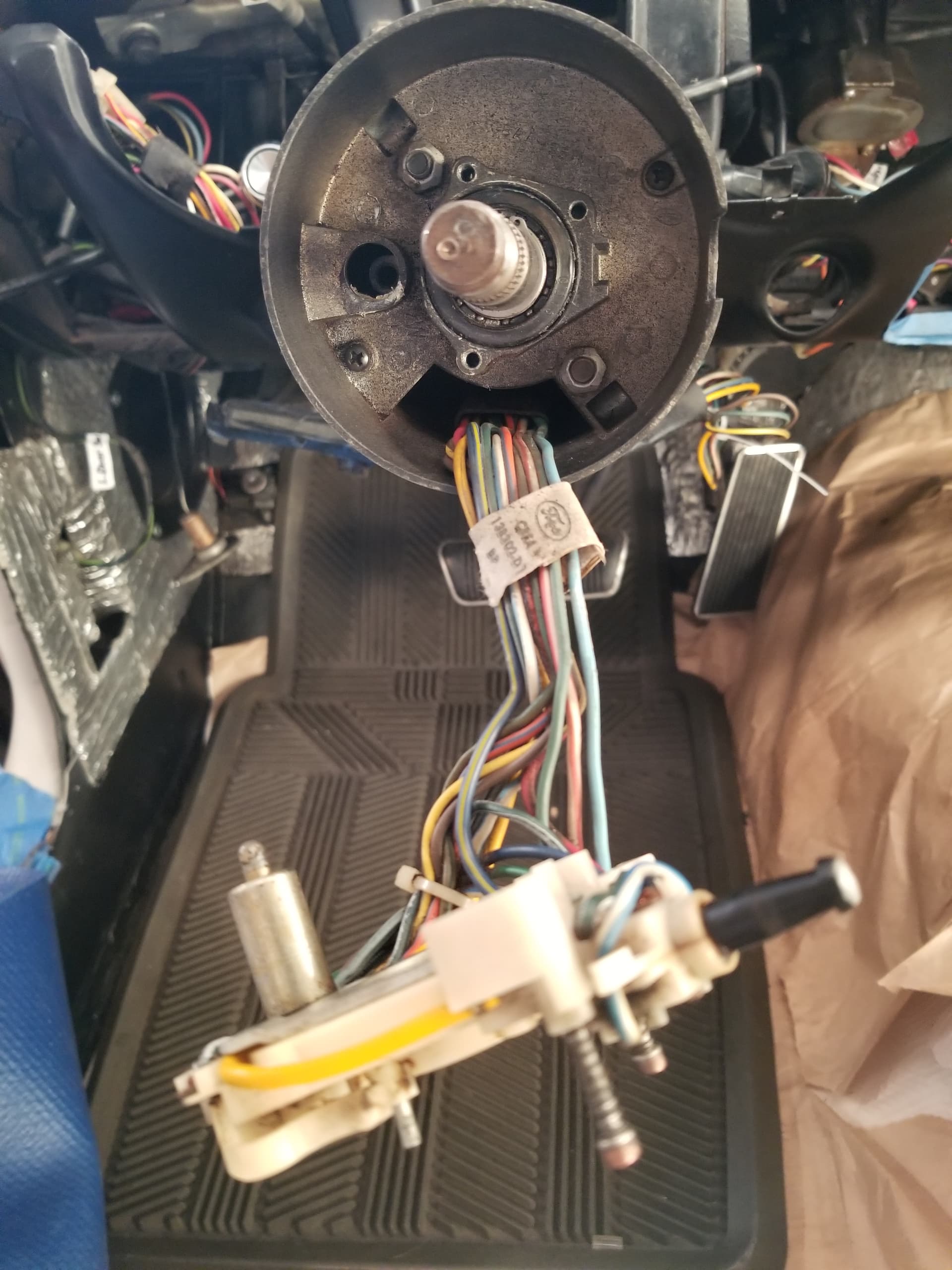
Quick follow up. I was able to remove my switch today. Nothing looks broke, the cams are complete, still had white grease near the turn signal wand hole. Some dirt that I cleaned out.
But, the big question and what started this was the Green/White wire issue. I did not see a Green/White wire in the run or at the switch. There is a dark green/white wire that jumps from the emergency switch over to the other side of the switch. I counted all the wire below at the connector and up at the switch and there were 12 total, counting the 3 for the speed control I don’t have that aren’t being used.
I looked through my whole Electrical Assembly Manual and couldn’t find any detail on the switch part number so I am enclosing a photo with the original paper label showing if that might help.
So, no green/wire cut up farther on the run as the wires are same as below. How could this be??
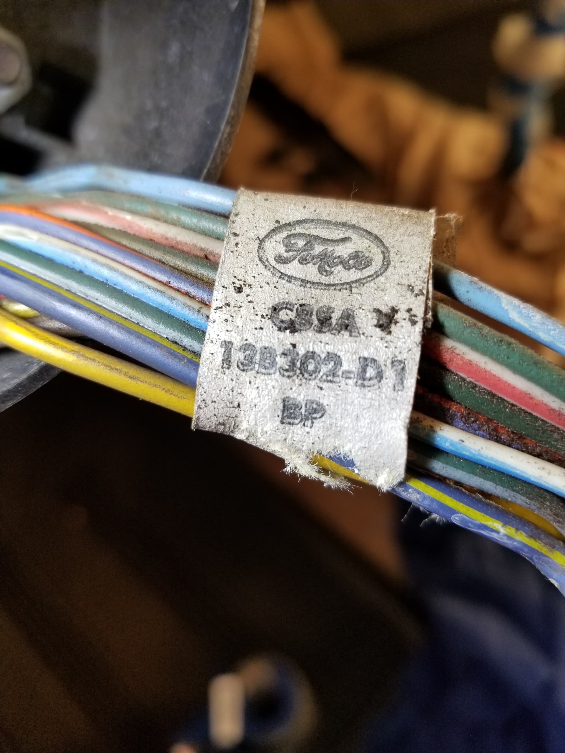

The green/white wire is in the bundle of your picture that shows the tag, in between the white/blue and blue/yellow wire. Follow it down the column to see where it goes.
Your switch is a (originally Thunderbird) service part that contains two extra wires: brown and yellow/black. They are not cruise control wires but are for the Thunderbird cornering light. On a Cougar, the cruise control wires are not part of the switch but a separate harness.
Wow, OK, is that common then to have that part # ?
Then why would I have 3 additional wires?
Yellow/Brown , Brown , & Dark Green/White(not sure if it is white or grey)
Then the follow up would be if that is the green/white, why would it not be hooked into the connector?
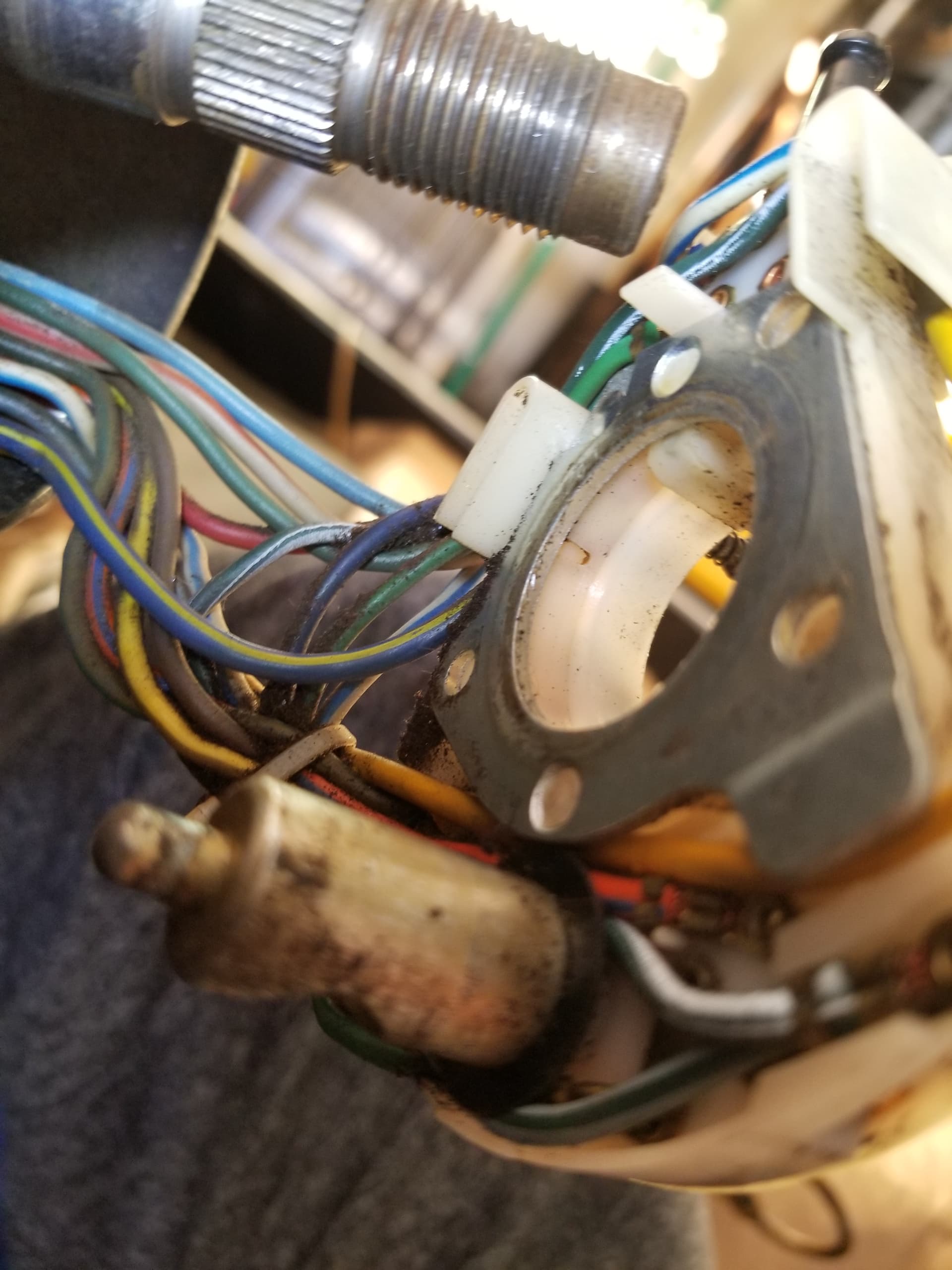
I went back down and took another look and a few photos.
I think that one of those 3 is indeed Green/White! ( just a darker green) I moved the wire around and found clean white for the stripe where most of it is dirty and faded!

The Thunderbird switch superseded the Cougar/Mustang switch in the '80s.
Your switch has already been replaced at least once.
The 3rd wire, dark green /white is the one to snap into the switch connector.
It should have a female pin that matches the male pin with the green/white and white wire.
It is common for there to be variations of the wire colors used. In this case, the original Cougar harness wire is a lighter green than the turn signal switch dark green/white probably due to the 20 years between the manufacturing dates. The wire colors Ford suppliers use come from a wide variety of wire manufacturers so there is not exact consistency between them. It is not unheard of for a component supplier to reverse the wire scheme (i.e. green/white → white/green) in order to make a delivery.
This is very good information and I hope will help the next guy in the future! I had no idea so it really helps cast some light on this situation! So the PO could not have had a working left turn signal?
I guess another question that came to mind is should I just put a new one (switch) in while i have it taken apart? I know the new ones run close to $100. But I am half way in at this point.
That way it should also be more correct with the wires and colors too.
Thanks Much!
Happy Thanksgiving!
Without the green/white wire connected from the switch to the car harness, the LH turn signal will not work.
Is it possible that these wires were connected together outside the connector shell and popped loose?
Locate the female pin from the switch, reconnect to the male pin, and test before replacing the switch.
Thanks for your reply. I do not have a pin on the wire . Where can I get these and what size would I need?
The Green/White wire on the harness side is currently spliced together with the White Wire and did have a metal connector to a single Green/White wire that wasn’t connected to anything. Should it be just the Green/White wire into the connector?
There was an after market stereo in here I took out 5 years ago when I started my restoration project and didn’t note wow it was connected.
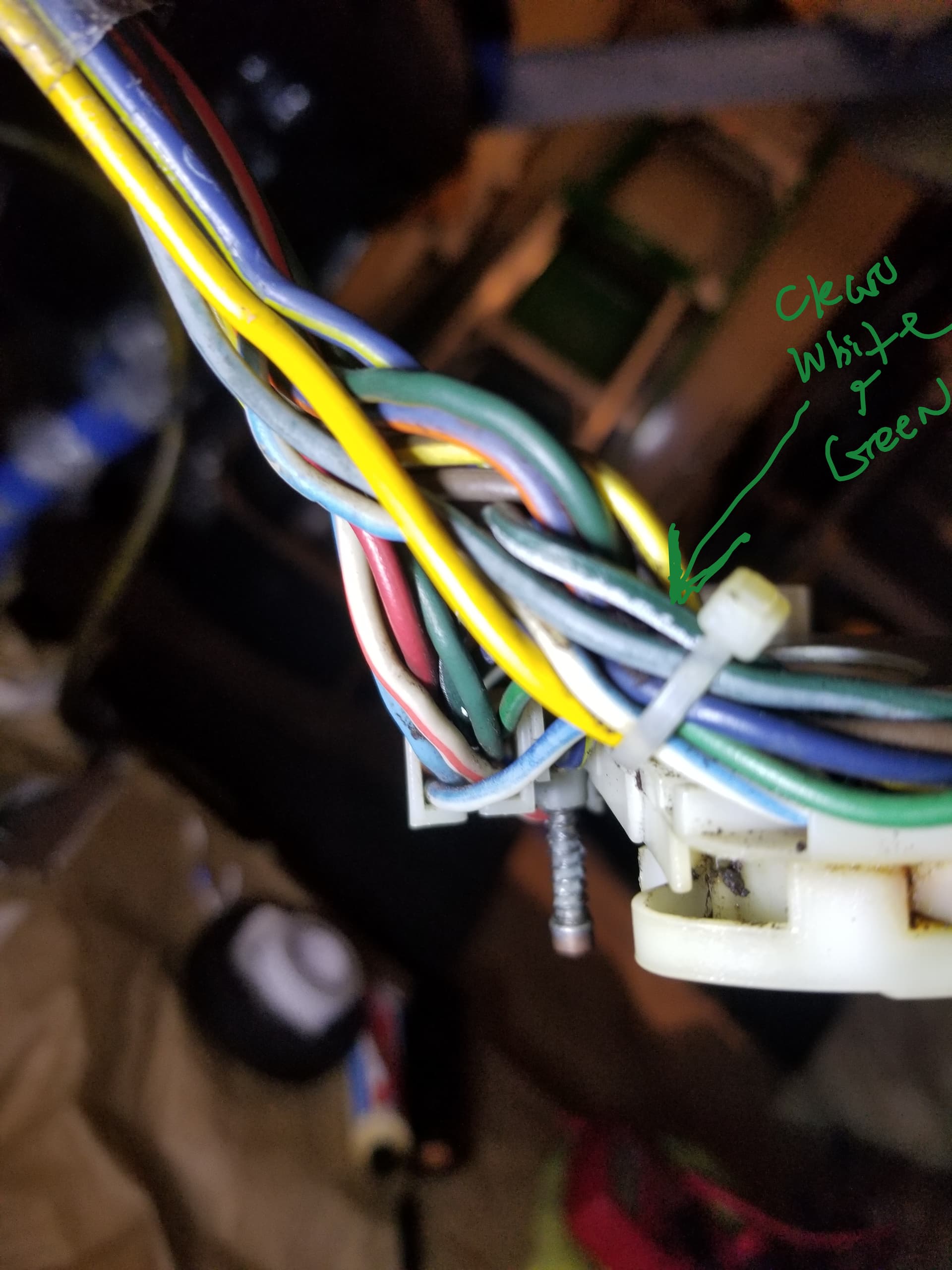
Here is a close up photo. does it look like the male/female pin that should have been in the connector? And the darker green wire just cut from the feed up the steering column? (like you suggested)

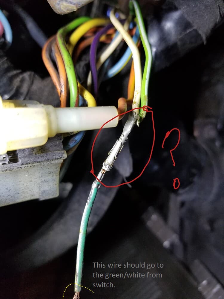
Where does the wire go? It should be connected to the green/white from the switch.
It is and was not connected to anything. That is why I asked. Should I just connect them or fix it so it goes through the connector?
Yes, that is the next step to try.
I was able to connect them today. I found that the Green/White wire from the switch did have male pin on it! It was covered with black tape. So when I removed the small single Green/White wire that was connected to the two wires, I had the open female connection needed and it just reached the other end. I have to admit I couldn’t test the switch yet as I have figure out what storage bin has my turn signal wand so will report back after that.
Sidebar on this topic. while i am getting ready to test my guage cluster, i was wondering how to get my courtesy lights tested? Should they turn on with the key in and turned left for accesory lights? or just pull out the light knob? none of them currently light up.
The courtesy light circuit does not go through the key. The center dash needs to be installed so the courtesy light toggle switch is in the circuit. Otherwise there is a fuse in the fuse panel. The door switches must be installed and functional.
Royce, i was thinking that after I posted this. Thank you for clarifying that.
Wanted to do a quick update. I have been waiting on a new turn signal wand and finally got that, I also ordered a new solid state IVR that I installed on the back of my dash cluster and hooked up all the wiring connections. I didn’t want to reinstall it at this point but just test all the new lights. I was pleased to see that they all work!
I tried my left turn signal, the Green/White wire that was a temporary mystery and big part of the topic of this chain, and that worked from the turn signal switch. I didn’t have the flashing light and clicking so assuming i still need another piece of the puzzle in place for that. I also have the new solid state turn signal Relay to still install and test so that will be next after i feel my turn switch is dialed in. My new wand felt stiff on making the left or right connection and my cancel cams weren’t working so i have to back that whole switch back out to see if something is binding or to tight,
My high beam light worked, and break lamp worked too. So feel good about the positive progress from all the help on here!
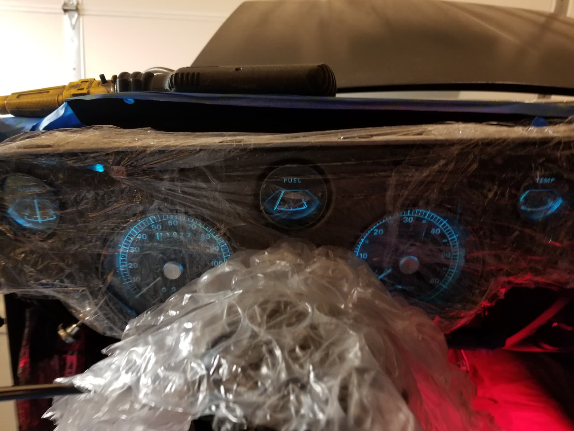
Next step is to use the new guage tester to determine if my guages are working correctly then i will move on to sequintial rear turn lights system in back. That should be some more fun. i cant wait to see how that goes. I am pretty close to thinking if there are any issues I might just pony up the money for the whole new solid state box solution! But not till I access if what i have will work first.