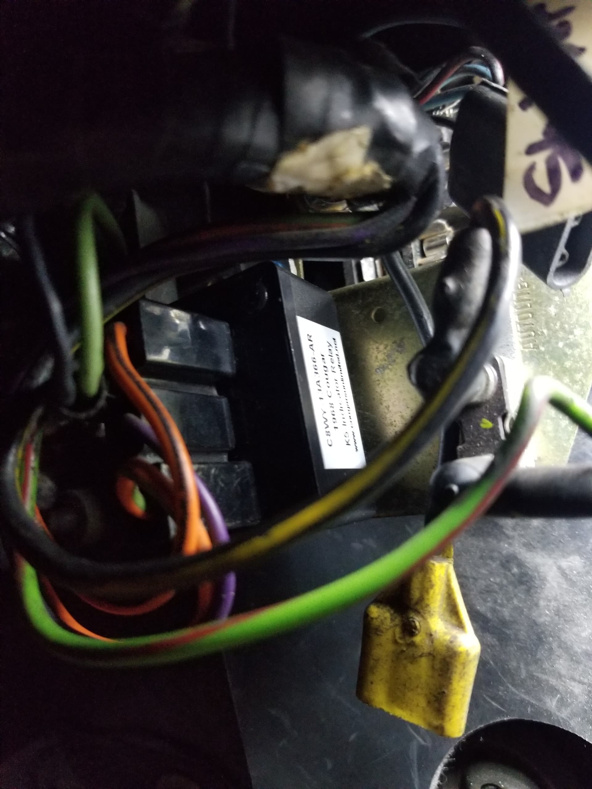
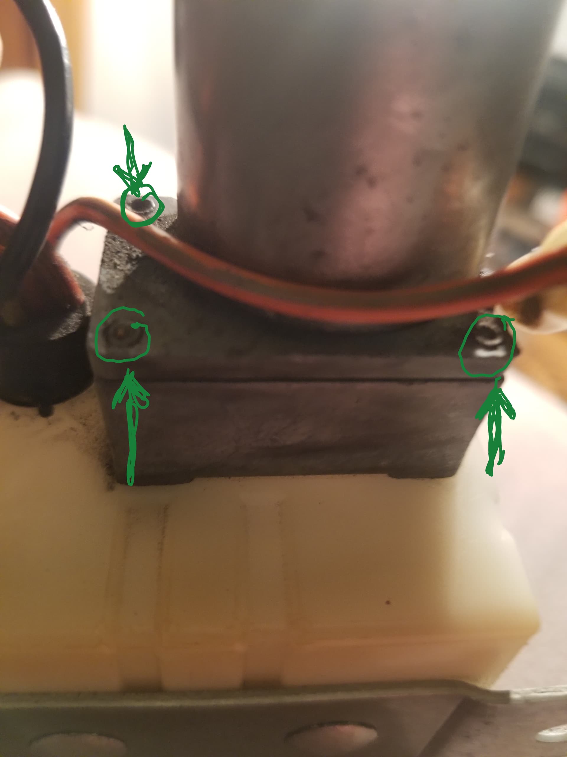
So I know my turn signal switch lights up the left & right arrow light on my dash. I am not getting flashing lights or clicking from the relay. So i did tackle installing my new solid state turn signal relay today. That was not a fun job due to difficulty accessing the two metal screws that hold it to the metal frame in front of the fuse box.
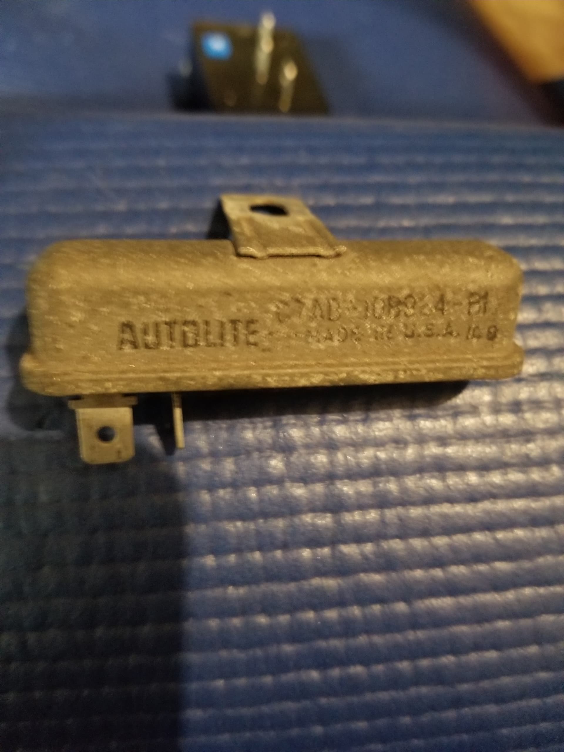
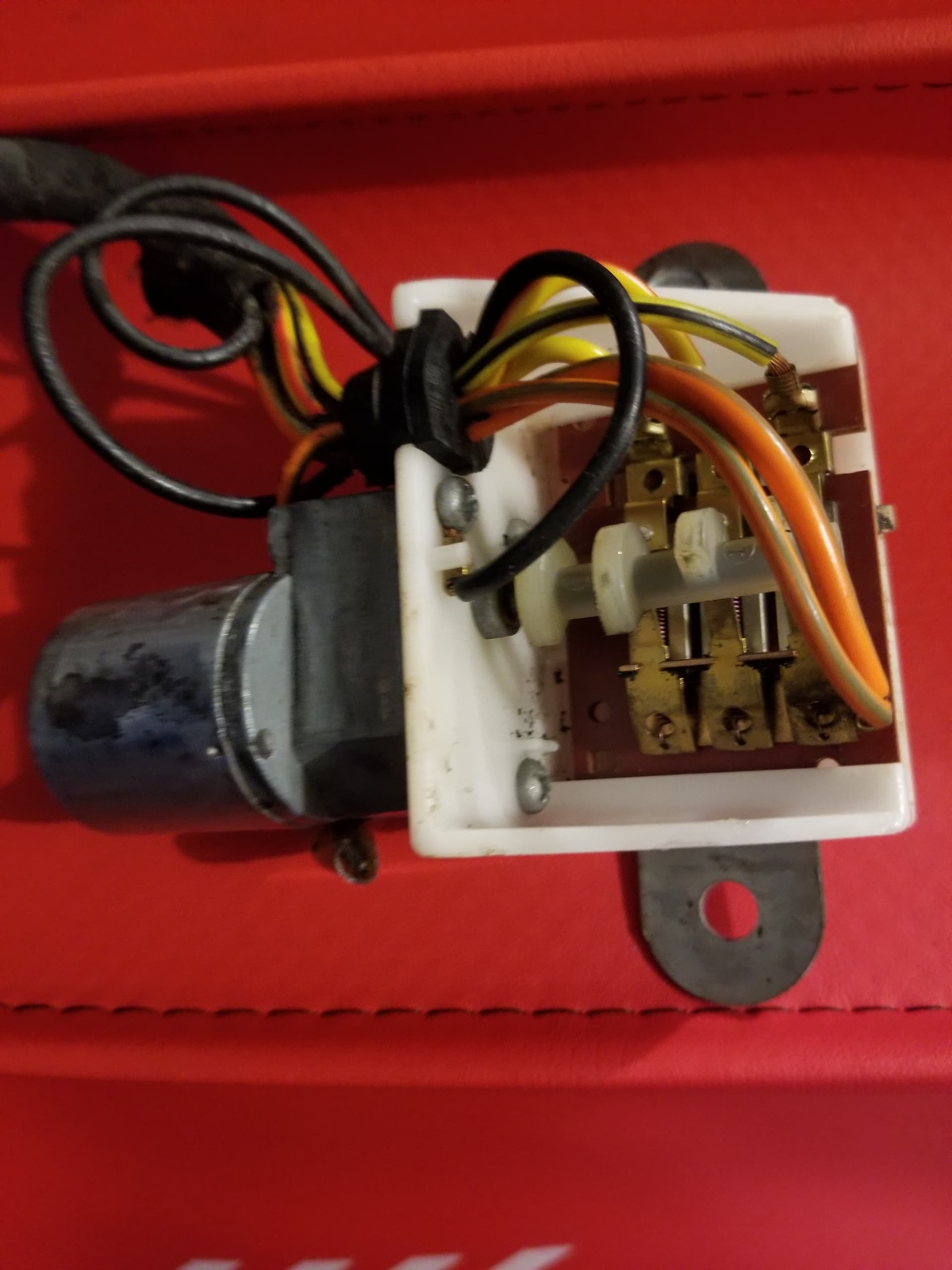
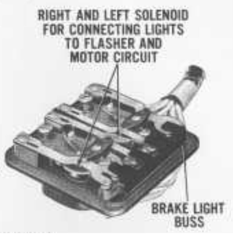
It is right behind the windshield wiper motor and where the main wiring loom comes through the fire wall. I noticed another long rounded relay secured with it that i have to admit I don’t know what it is for? (see pic) When i finished i still had no flashing arrows or clicking.
So my question is there something else needed to complete the test for the turn signals? I do not have any of the turn lights connected yet as I was hoping I could just validate they work without having them all connected,
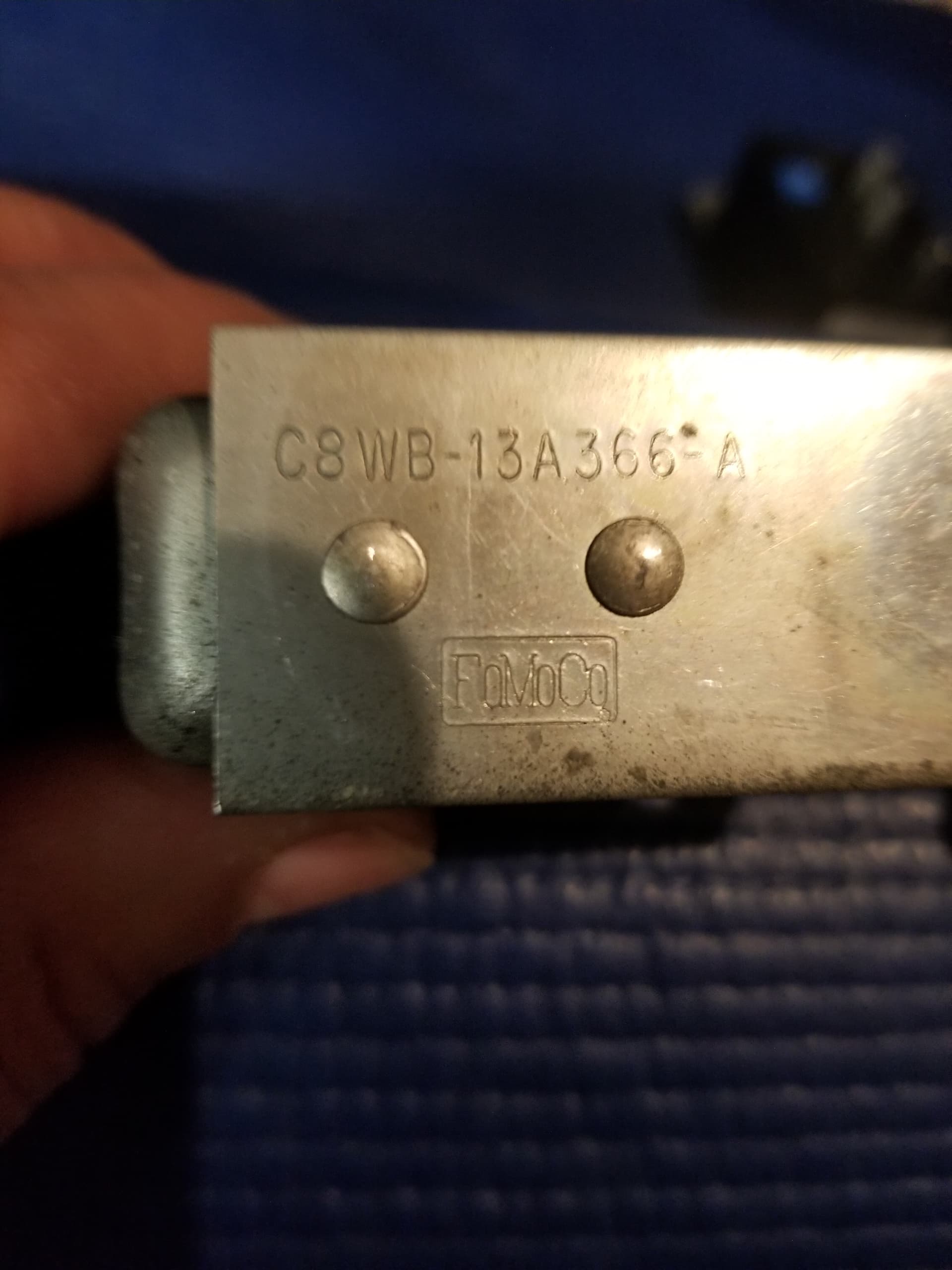
The 1967-68 Cougar indicator relay is a current-sensitive relay - it is triggered by the current passing through the two outer pins to the lights. The 1968 C8WB-13A366-A OEM relay trigger current is 6-7 amps. The late '68 C8WB-13A366-C threshold is 7-8 amps.
I have never seen an explanation why Ford increased the trigger current for this relay in late 1968 - the original relay typically failed to trigger with the A/C, headlights, and brake lights on at the same time.
The (adjustable) electronic relay threshold is set to 150-200 ma so it will work with LED or incandescent bulbs. You must connect at least one bulb to the sequential controller for it to operate.
Thank you for that explanation, i sensed I was missing a piece and now realize why the need to have the sequential relay involved. I had just not got that far yet so if i dig out one of the tail lights and hook it up in the trunk I should then be able to complete the path for that signal and see if it will work.
I have connected my front turn lights, my rear turn lights, and all wires in my trunk for the sequential system. When I turn my lights on, my dash lights all work and all my turn lights are on (front & back). If i activate my turn signal, the dash indicators are both on but not flashing, the sequential motor is working, but no left or right turn flashing, just lights. I started a new thread for that but no one has chimed in to comment. I realize the complex nature of this but need some help where to look next.
I checked my turn signal switch again for continuity through the emergency switch which was good. Battery power is good, in-line fuse good as I worked through the suggested troubleshooting.
I have been studying the write ups on this and just sure what to do next.
Since the sequential motor is running, the power path from the turn signal switch through the 459 orange/green stripe wire to the motor is good. It is quite common for the original sequencer contacts to be carbon contaminated and not pass current through over to the directional relay (with 14 wires).
Check the output of the sequential motor on the the 436 yellow, 438 yellow/black, and 437 yellow/red wires. No flashing power is typically due to oxidized contacts.
Then check for 12V power on the white (440 left turn) or the violet (441 right turn). These signals cause the directional relay to pass the signals onto the correct side and front lights. No right or left 12V power can be a bad (open) turn signal switch or broken/disconnected wires. There are two plugs for these two wires: behind the RF kick panel, and the back of the LR inner fender (in trunk). No power out of the relay typically is a stuck (rusted) contact arm, oxidized contacts, or burned-out (open) relay coil.
Thank you so much for your reply. I have been reading as much as I can written about this and just keyed in on the power to the White or Violet wires last night so glad to hear I was tracking right.
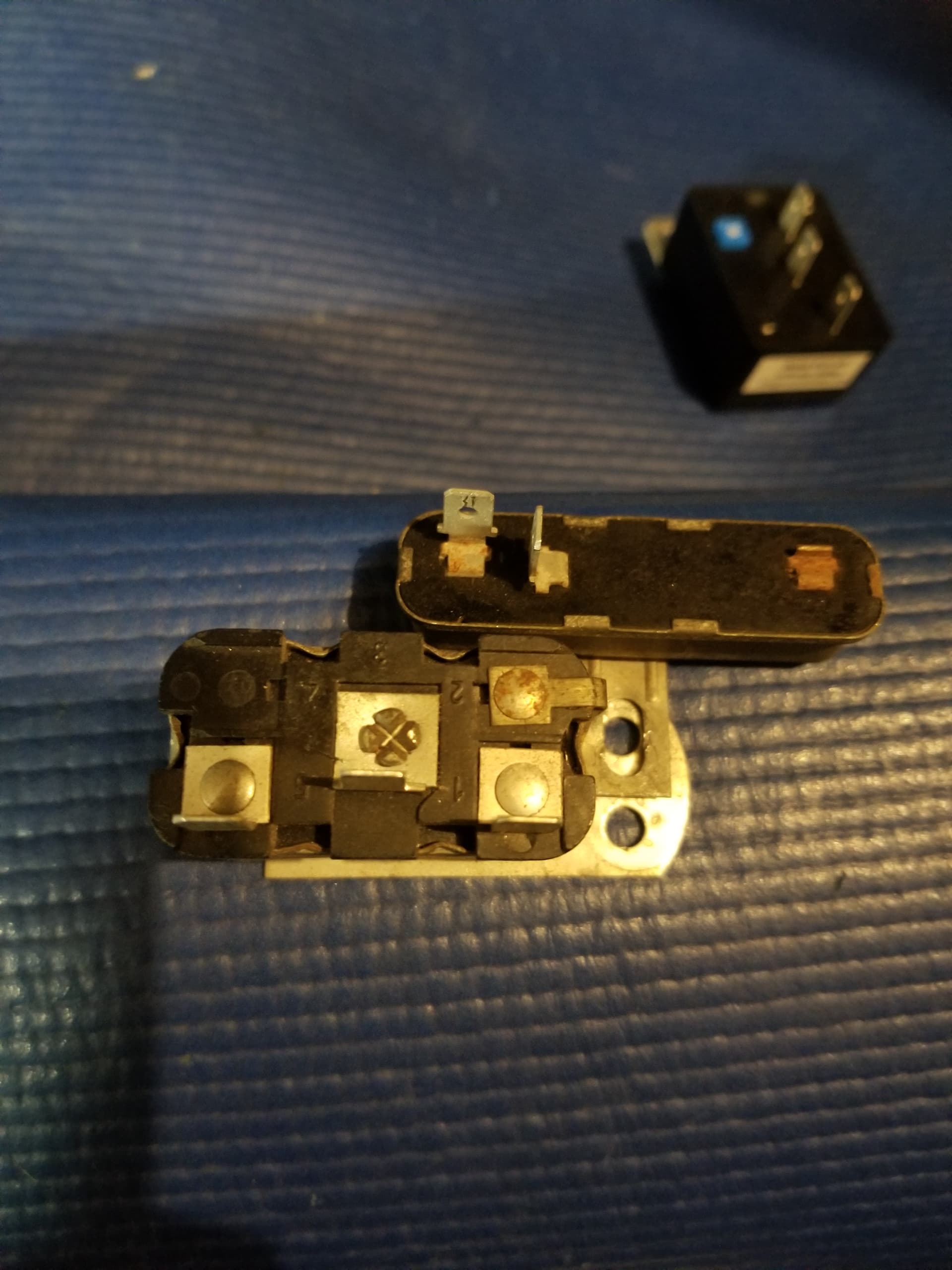
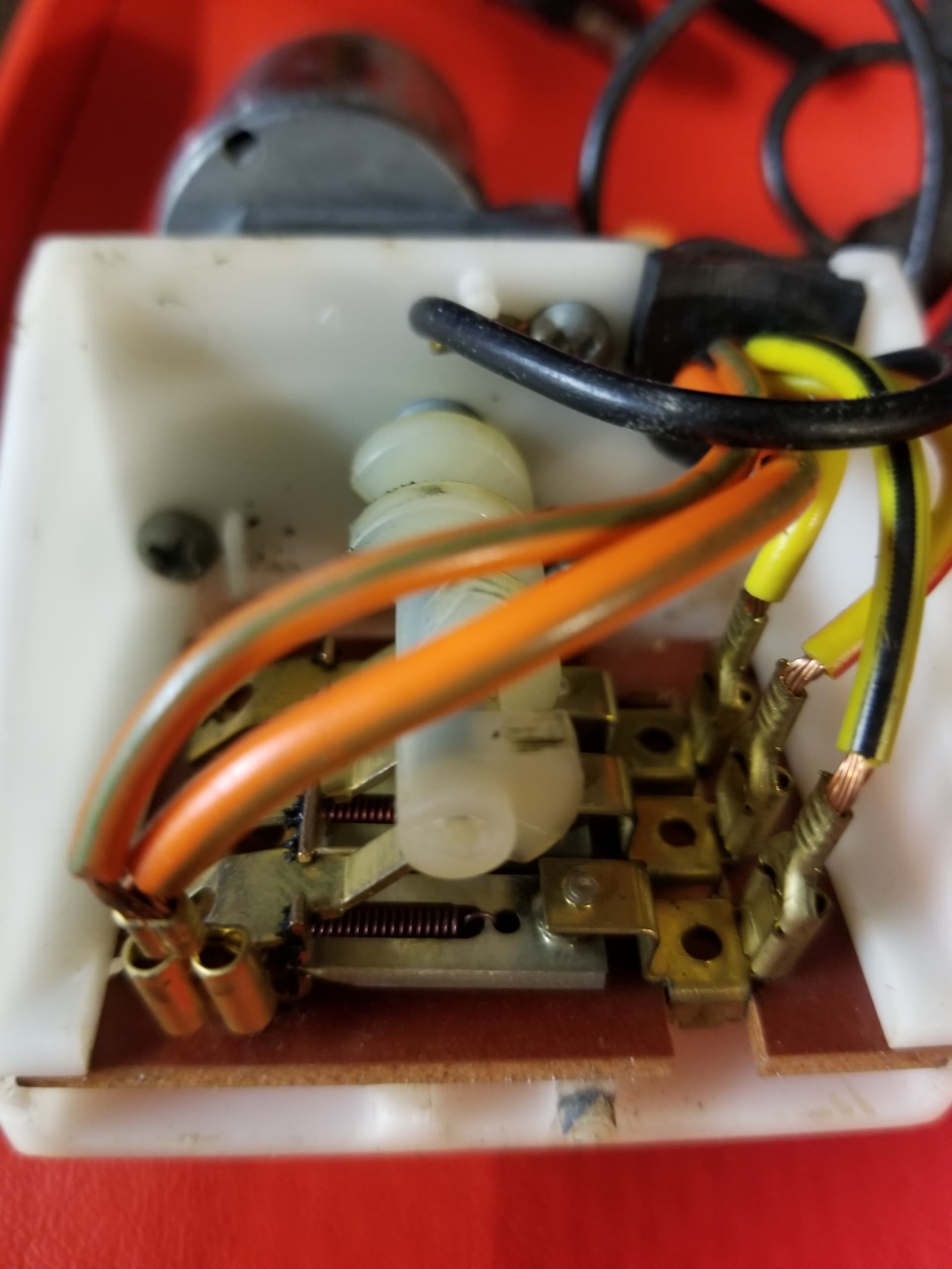
I did inspect the small connections that the cam makes to activate the individual connections in order. It is actually ingenious to me to watch the magic happen (when it will work)! I was quite surprised how clean all the brass contacts looked. I could be missing something but thought I was good. (see pic)
I will definetly check those two plugs you mentioned to as I had not done that. This is all new to me so thanks for your patience.
I will report back in a day or two on this.
Check the contacts with a voltmeter or test light during turn signal operation.They may look shiny from the outside but the actual contacts could be burnt black with oxidation - which will not pass current.
One follow up question on the two plugs you mentioned checking.
These have the White & Violet wires in them correct? White on LR and Violet on RF? These should be hot correct when I activate a right or left turn signal?
I have a few days off coming so hope to tackle this soon.
Had a few minutes today to get my turn signal switch reinstalled again after pulling it back out to check continuity through the emergency switch. Then turned on the lights to check for 12v on the white and Violet wires on K8/K9. I did validate power to each.
When i turned on my left blinker i went back to check voltage on the sequential motor while it was operating and validated 12v at the Orange/Yellow wire then the motor just quit, I could still get 12v on the IN side and one of the three connectors that was still connected had power. Since the motor quit, I was not able to test the other two connectors. Not sure why the motor quit so will have to check into that. So far everything had power. That is far as i got today but was encouraging. Hope my motor didnt just peter out. Any way to just change the motor out?
Try rotating the cam CCW gently with a pair of pliers. It will be very stiff to turn. Typically, the motor has stopped on a section where the armature has a dead winding. If there is rust in between the motor case magnets and the armature, Royce’s suggestion may help but oil is an insulator and is bad for electrical brush contact.
The version you have must have the rivets drilled out in order to remove the motor from the gearbox. Later (~1972) motor versions were held on with screws. Crimped detents hold the motor outer casing to the motor. Again, later versions were held on with screws.
Internally, the motor is similar to that of a slot car. I’ve never had any luck rewinding the motor and getting the brushes realigned once it was taken apart.
Bad motor and contacts: time to replace the sequencer with an electronic version!
I had a couple of questions on this.
Should I just start by removing the motor casing by loosening the crimps?
So I would have to drill out the tiny rivets to remove the motor from the gear box, correct?
Also, how can I check to see if I caused the 15 amp circuit breaker to trip? (I don’t think I would still show power at the contacts though if that happened)
And what about the other 5 amp circuit breaker in the driver side rear cowl area? How to test if that is still good?
Yes, you must drill out the two rivets to release the motor from the gear box.
The 15A fuse is located up under the dash, to the right of the steering column. It is a white twist-apart fuse holder in an orange/yellow wire. If the fuse is popped, no voltage will be found on the orange/green wire in the trunk (and no turn signals).
The 5A circuit breaker in the trunk is for the rear running lights only. It has no impact on the turn signals. It will measure as a short across the two black wires when working correctly.
First, double check the motor by applying 12V to the orange/green wire directly (ground to the case of the gear box).
Then unplug all 4 of the quick disconnect wires (note their location).
Slide out the switch board - don’t let the cam catch the switches.
Pull the white nylon cam off the shaft.
Unsolder the orange/green wire.
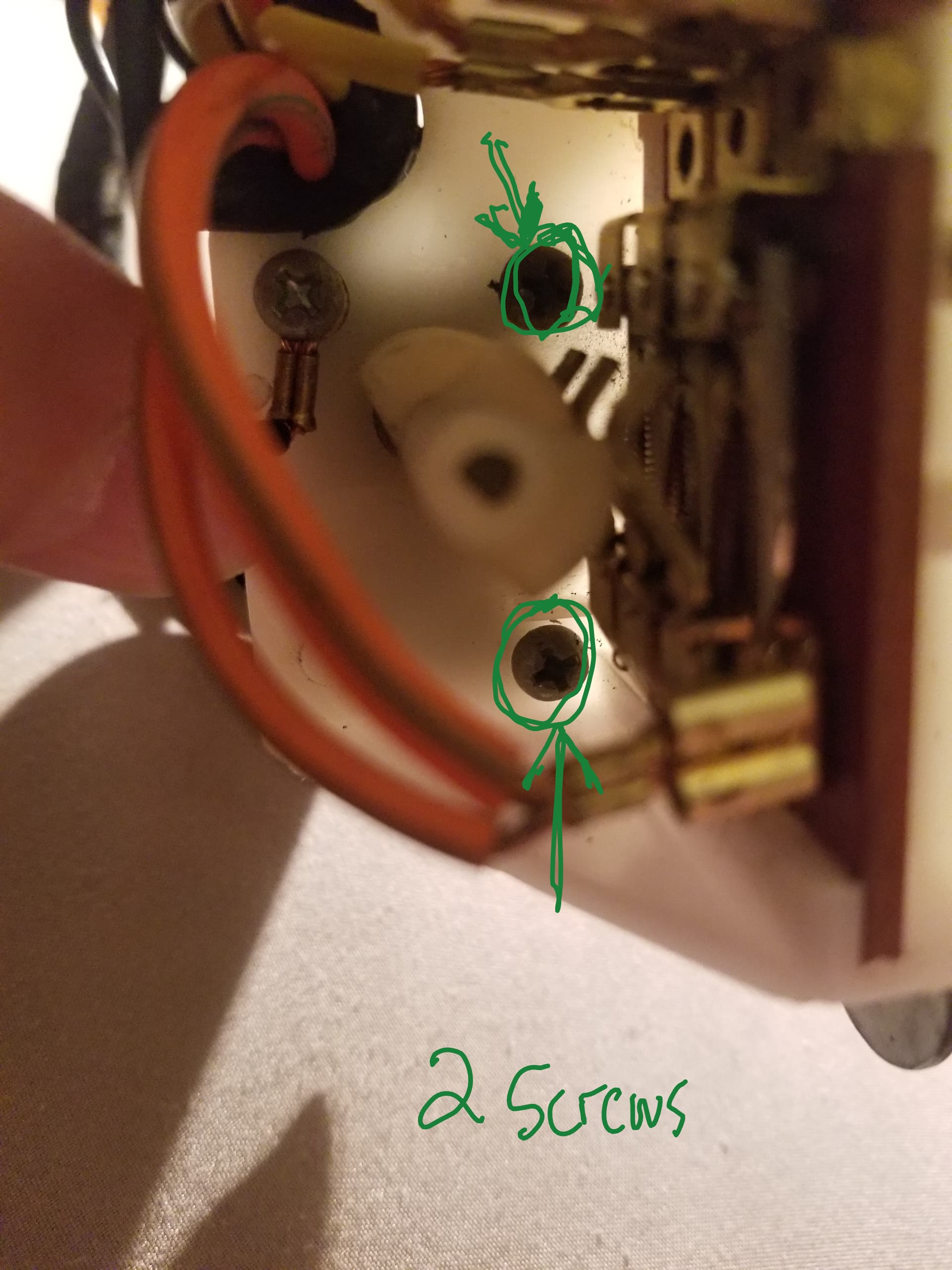
Remove the two screws holding the gear box to the white plastic housing.
Drill out the rivets and remove the motor.
The grease in the gear box is probably dried out.
Great directions, exactly what I needed.
I took a step to find another working motor. I am going to pause on rebuilding/fixing mine for now until I know any other issues are addressed.
So, with that issue out of the equation, and now knowing my alternate is working, here is my current status:
Motor working
Sequencer has power to Orange/Green wire coming in.
Power on each contact when motor turning in sequence.
K8/K9- Violet has power for right, White getting power for left.
Emergency Flasher- Blue wire has power, Yellow has flashing power when emergency button activated.
All tail lights are on, no sequential turning, no Emergency flashing
Front lights all on, No turning signal, or emergency flashing up front.
So, I am now thinking that the K8/K9 relay has power but not operating correctly?
I need your expert opinion for next step!
Do you have brake lights?The K8/K9 relay may be stuck in the brake light mode.
You should hear each side of the relay clunk down when power is applied to the violet or white wire and ground to the case.
Test the resistance of each coil to the case ground - it should be around 45-60 ohms.
If the coils are good, the relay can be opened for inspection.
Carefully, pry up each one of the tangs holding the relay body to the case. The ground tang must be desoldered with a 100W iron.
Then inspect for rust or a broken contact arm keeping a relay section from operating. The relay contacts can be cleaned using a relay contact burnishing tool (such as GC Electronics 9338).